4 TECHNICAL DATA
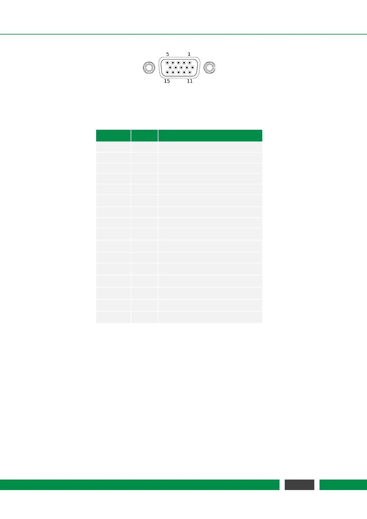
D-SUB-15-HD connector to external Hand Control Module
Table 4.6 – Pin Assignment
Pin Signal Function
1 GND Ground
2 d.n.c. DO NOT CONNECT
3 d.n.c. DO NOT CONNECT
4 d.n.c. DO NOT CONNECT
5 d.n.c. DO NOT CONNECT
6 3.3V Power supply, 3.3V DC
7 d.n.c. DO NOT CONNECT
8 GND Ground
9 SyncB Internal sync line
10 5V Power supply, 5V DC
11 Switch Power switch
12 RXD+ Differential data for receiving
13 RXD- Differential data for receiving
14 TXD+ Differential data for transmitting
15 TXD- Differential data for transmitting
Shielding GND Ground
4.2.4 USB Connector
The USB Type B connector offers direct connectivity e.g. to a PC for software control of the MCS2.
The USB interface is galvanically isolated to the internal ground of the controller.
4.2.5 RJ-45 Connector for Ethernet Communication
The RJ-45 connector at the MCS2 main controller provides a standard 10BaseT / 100BaseTX ether-
net interface for software control of the MCS2.
25
MCS2 User Manual