2 PRODUCT OVERVIEW
Table 2.1 – Continued from previous page
Product Code Description Connectors
MCS2-C-0017 3 channel Controller, I/O Module
Type 4, USB interface
USB type B, D-SUB-15 female (Sen-
sor Module), D-SUB-37 female (IO) 1x
BNC (1 in)
MCS2-C-0018 3 channel Controller, I/O Module
Type 4, Ethernet interface
RJ-45 Ethernet, D-SUB-15 female
(Sensor Module), D-SUB-37 female
(IO) 1x BNC (1 in)
MCS2-C-0019 9 channel Controller, I/O Module
Type 3, USB interface
USB type B, D-SUB-15 female (Sensor
Module), 4x BNC (3 out, 1 in)
MCS2-C-0020 9 channel Controller, I/O Module
Type 3, Ethernet interface
RJ-45 Ethernet, D-SUB-15 female
(Sensor Module), 4x BNC (3 out, 1 in)
MCS2-C-0021 3 channel Controller, I/O Module
Type 6, USB interface
USB type B, D-SUB-15 female (Sensor
Module), D-SUB-37 female (IO), USB
type B (HSDR)
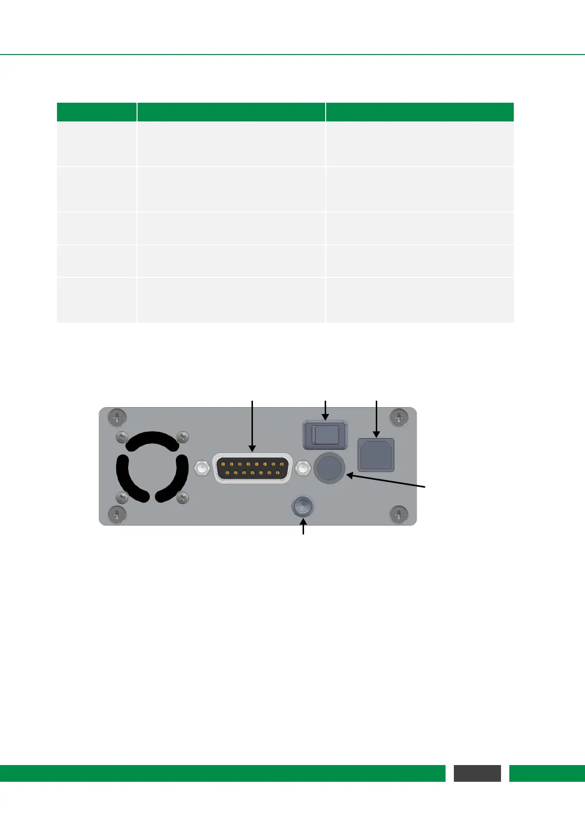
The connectors of the most common MCS2 controllers are shown in the following figures.
Ground Pin
Power
Switch
USB
Connector
12V Power
Supply
Connector
Sensor Module
Connector
(D-SUB-15)
Figure 2.2: Three Channel MCS2 Table Top Housing (front view)
Depending on the computer interface the arrangement is a bit different. Controllers with more
channels that are delivered in a table-top housing have the same connectors as in the figures, but
are equipped with additional D-SUB-15 connectors to the sensor modules.
13
MCS2 User Manual