HAT600N Series ATS Controller User Manual
HAT600N Series ATS Controller Version 1.1 2019-09-05 Page 7 of 24
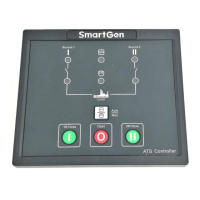
1# Volt normal
2# Volt normal
Gens Start signal Out
Gens starting
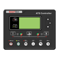
PWR 329kW
PF 1.00 PS 329kVA
2010-06-10 (4) 20:25:36
Present Status: MANUAL
5. LCD DISPLAY
5.1 MAIN SCREEN
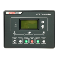
This screen shows: line-line voltage (L1-L2, L2-L3, and
L3-L1), frequency and controller’s present working
mode.
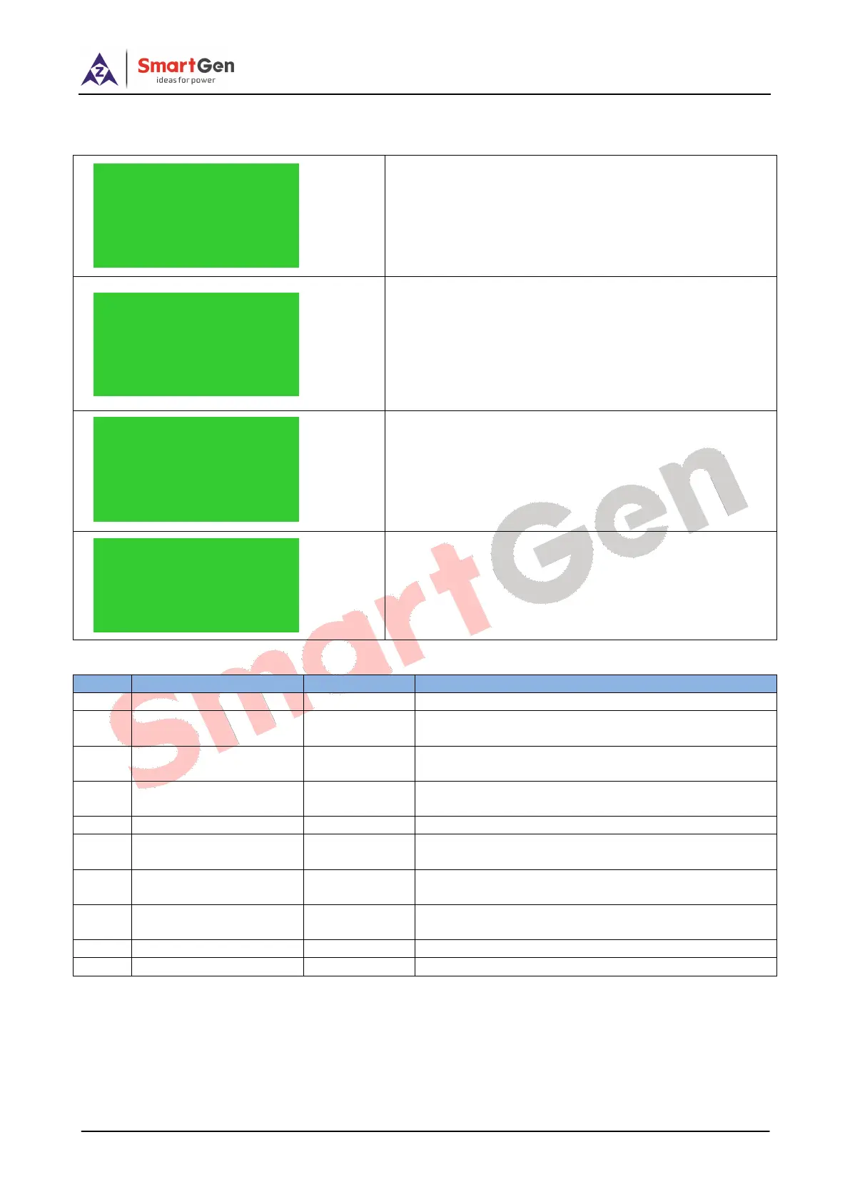
This screen shows: 1# and 2# 3 phase Voltage (L-N), 3
phase current with load and controller status.
This screen shows: total active power, total apparent
power, power factor and real-time clock and controller
working status.
First line: 1# operating state of power supply.
Second line: 2# operating state of power supply.
Third line: other operating states.
Fourth line: alarm type and information.
Table 5 Display of #1 Status (upper to lower)
When 1# genset occur failure, this will display.
When 1# breaker occur closing failure, this will
display.
When 1# breaker occur opening failure, this will
display.
When 1# power supply voltage is higher than the
setting value, this will display.
Loss of any phase of A, B and C.
When 1# power supply frequency is higher than the
setting value, this will display.
When 1# power supply frequency is lower than the
setting value, this will display.
When 1# power supply voltage is lower than the
setting value, this will display.
Phase sequence is not A-B-C.
1# source voltage is within the setting range.
U1(L-L) 380 380 380V
U2(L-L) 380 380 380V
F1 50.0Hz F2 50.0Hz
Present Status: MANUAL
U1(L-N) 219 219 219V
U2(L-N) 219 219 219V
AMP 500 500 500A
Present Status: MANUAL