Basic information about the device
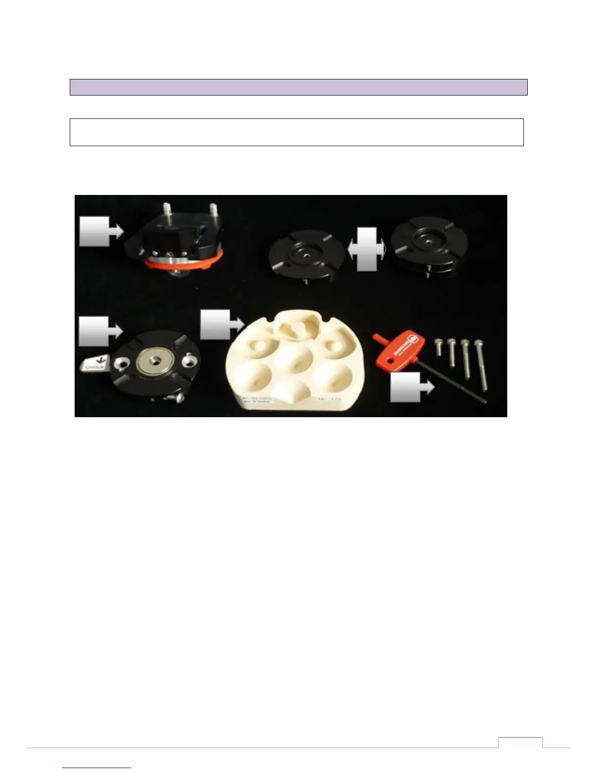
Figure 25: individual parts of the object holder
1.
Removable object holder for non-articulated jaw models. The model is fastened on the object
holder using a clamp. This clamp is fastened or released using the hex key (5).
2.
Three additional spacer plates for height alignment.
3.
The locking plate is screwed onto the spacer plates. The locking plate must always be the last
plate to be screwed to the spacer plates. A recess has been cut into one side of the spacer
plates and of the locking plate so that the plates can be assembled correctly. The locking
plate is fitted with a magnet, and acts as the connection piece with the object holder. There is
also a lock on the plate for the fixator available in the optional accessories.
4.
Calibration block for axis and 3D calibration.
5.
Hex key for clamping or loosening the plaster model on the model holder or the fastening
screws. Use the fastening screws to attach the locking plate to the spacer plates located
underneath on the system base plate firmly attached in the scanner.
11.3 Object holder
Individual parts of the object holder
The scope of delivery for the object holder of the Activity 885 consists of the following components: