- 12 -
No.JXC※-OMW1019-A
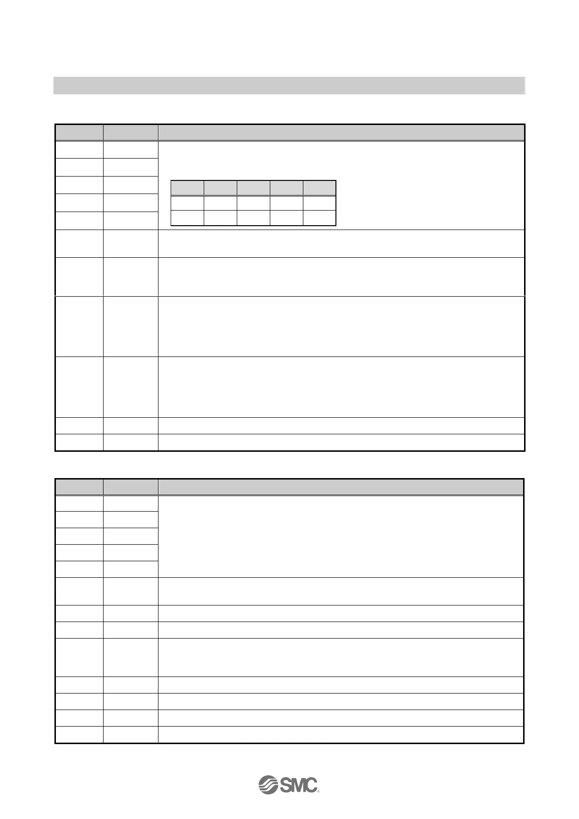
(2) When the MODE input (Terminal No. A8) is ON
- Input terminal-
Step data instruction bit No. for writing the current position
(input is specified by combination of IN0 to IN4.)
Example: (Bit no. to specify the step data no.3.)
The input / output signal functions are changed using this terminal.
This table shows the case when the MODE is ON.
Teaching instruction signal
When the teaching instruction signal is ON, the current position is written to the
specified step data between IN0 and IN1.
When SVRE output is turned ON, the table moves in the positive direction in
accordance with the operation parameters “JOG speed” and “JOG acceleration”
while the JOG+ input is turned ON.
When ALARM and SVRE are turned ON, it is possible to instruct the JOG operation,
regardless of the SETON ON / OFF condition.
When SVRE output is turned ON, the table moves in the negative direction in
accordance with the operation parameters “JOG speed” and “JOG acceleration”
while the JOG- input is turned ON.
When ALARM and SVRE are turned ON, it is possible to instruct the JOG operation,
regardless of the SETON ON / OFF condition.
Same as the description when the MODE (terminal No. A8) is turned OFF.
Same as the description when the MODE (terminal No. A8) is turned OFF.
Indicates the MODE input status.
This table shows the case when the MODE is OFF.
Same as the description when the MODE (terminal No. A8) is turned OFF.
*3
)
Same as the description when the MODE (terminal No. A8) is turned OFF.
Signal for showing the completion of the teaching data writing. This terminal turns
ON when writing of the current position is complete after turning ON the WRST. When
the WRST is turned OFF, WREND is also turned OFF.
Same as the description when the MODE (terminal No. A8) is turned OFF.
Same as the description when the MODE (terminal No. A8) is turned OFF.
Same as the description when the MODE (terminal No. A8) is turned OFF.
Same as the description when the MODE (terminal No. A8) is turned OFF.
*3) The signal will be unstable (chattering occurs) in the JOG operation due to the lower speed of operation.

 Loading...


