MENTOR 12 USER’S MANUAL SECTION 3: ADVANCED CONTROL – Page 51
FAULT in terms of its electrical parameters (values and
angles) and in the state of the binary outputs (to simulate the
state of any device outside the relay, such as the high
voltage switch). The maximum duration of this state can also
be configured. Unlike the pre-fault state, where the only
conditioning factor to change to the next state (Fault) is for
the time established for this condition to elapse, in this case
the change to the next state generally occurs due to the
binary input condition defined on the TRIP button being
satisfied, and if this does not occur, because the maximum
time defined for the state has elapsed. If the expected trip
occurs, the function returns the time that it took for the trip to
take place from the moment when the Fault state began,
presenting this as a test result.
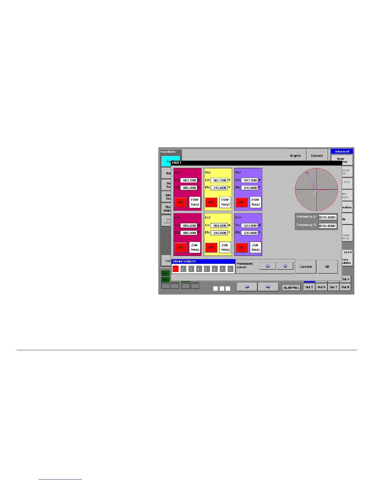
You can access the screen to configure these values by
pressing the RED colored button, marked “fault”. A screen
appears where you must enter the desired levels and angles
for the power outputs (See Output Value Selection in Section
1 Basic Control) and also the logic states for the digital
outputs.
 Loading...

