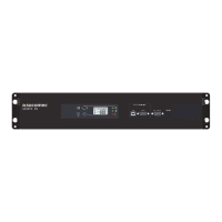
7
STATYS 200-1000A - Ref.:OPMSTA200910-GB_06
ENGLISH
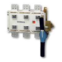
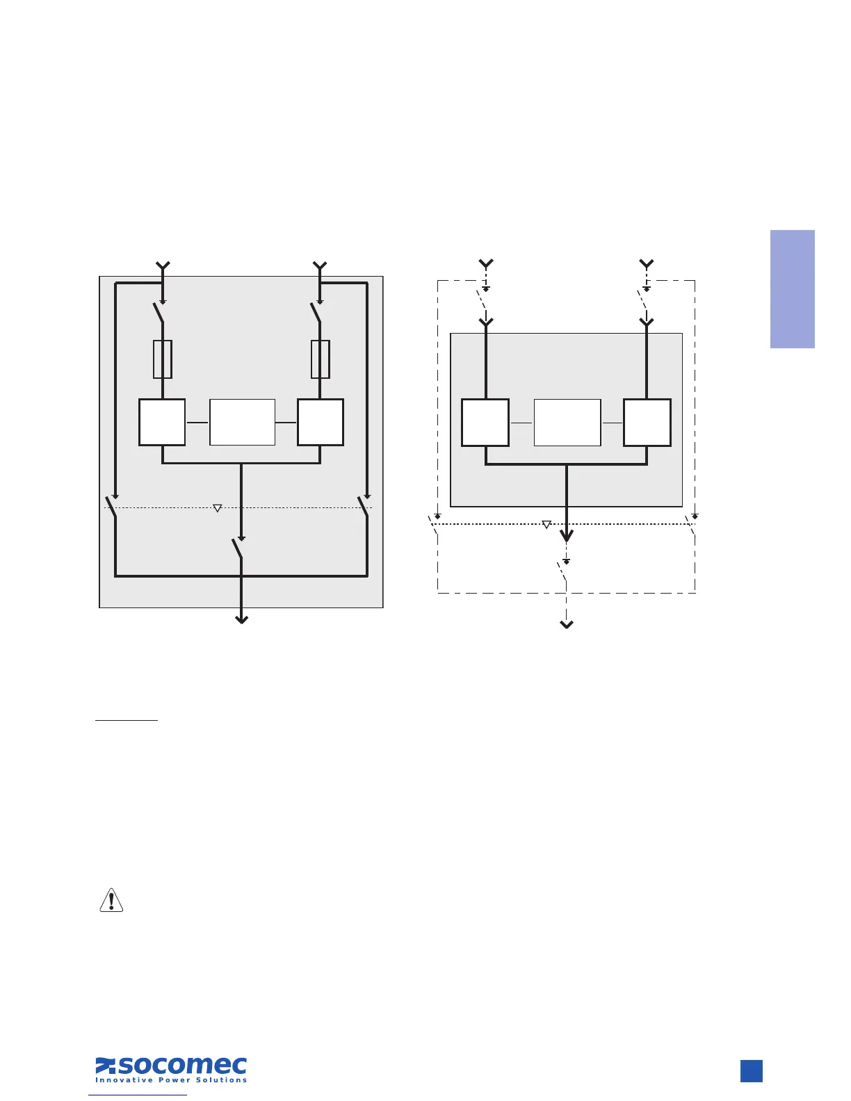
6. FUNCTIONAL DIAGRAMS
Source 1
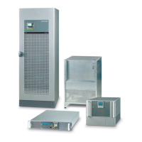
Cabinet Integrated
Load
Source 2 Source 1
Load
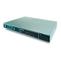
Integrable chassis
Source 2
LEGENDS:
Q41 = Source 1 input switch*,
Q42 = Source 2 input switch*,
Q30 = Output switch*,
Q50 = Inverter, for source 1 or 2 maintenance bypasses*,
CS1 = Static Switch 1,
CS2 = Static Switch 2,
F = Protection by Fuse (optional),
- -- - and * = Supplied to customer in Integrable version.
* = optional
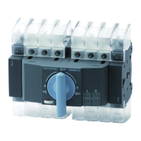
CS1
Logique de
commande
CS2
Q50-1** Q50-2**
Q30
Q42Q41
STATYS
F*
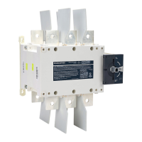
CS1
Logique de
commande
F*
CS2
Q50-1** Q50-2**
Q30
Q42Q41
STAT YS
** = Q51 and Q52 for Statys 800/1000A