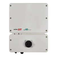
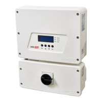
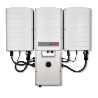
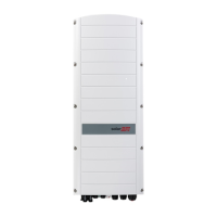
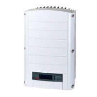
replacing the connection unit (see
Figure 32
:
a. Pull the DC wires through the Connection Unit openings and wrap them twice
around the ferrite ring, then tighten with a cable tie. Using a Philips screwdriver
connect the DC+ and the DC-.
b. Pull the RS485 and/or Ethernet wires through the Connection Unit openings.
Wrap the wires twices around the ferrite ring and tighten with a cable tie.
Connect to the RS485-1 terminal: B=Yellow, A=Green and G= black.
c. In the inverter, connect the Meter wires , if available to the RS485-1 terminal.
d. Pull the AC wires through the inverter openings, then using a Philips
screwdriver connect the AC wires (see
Figure 32
.
12.
Reconnect the AC wires conencting the distributing panel to the terminal block
according to the labels and reconnect the DC cables to the MC4 connector.
13. Close the Connection Unit and inverter covers, fasten the Connection Unit bracket
using a standard bolt.
14. Perform the commissioning steps as described in
Activating, Commissioning and
Configuring the System
on page 35.
EV Charging Single Phase Inverter Guide MAN-01-00583-1.5
76 Replacing the Connection Unit
 Loading...

