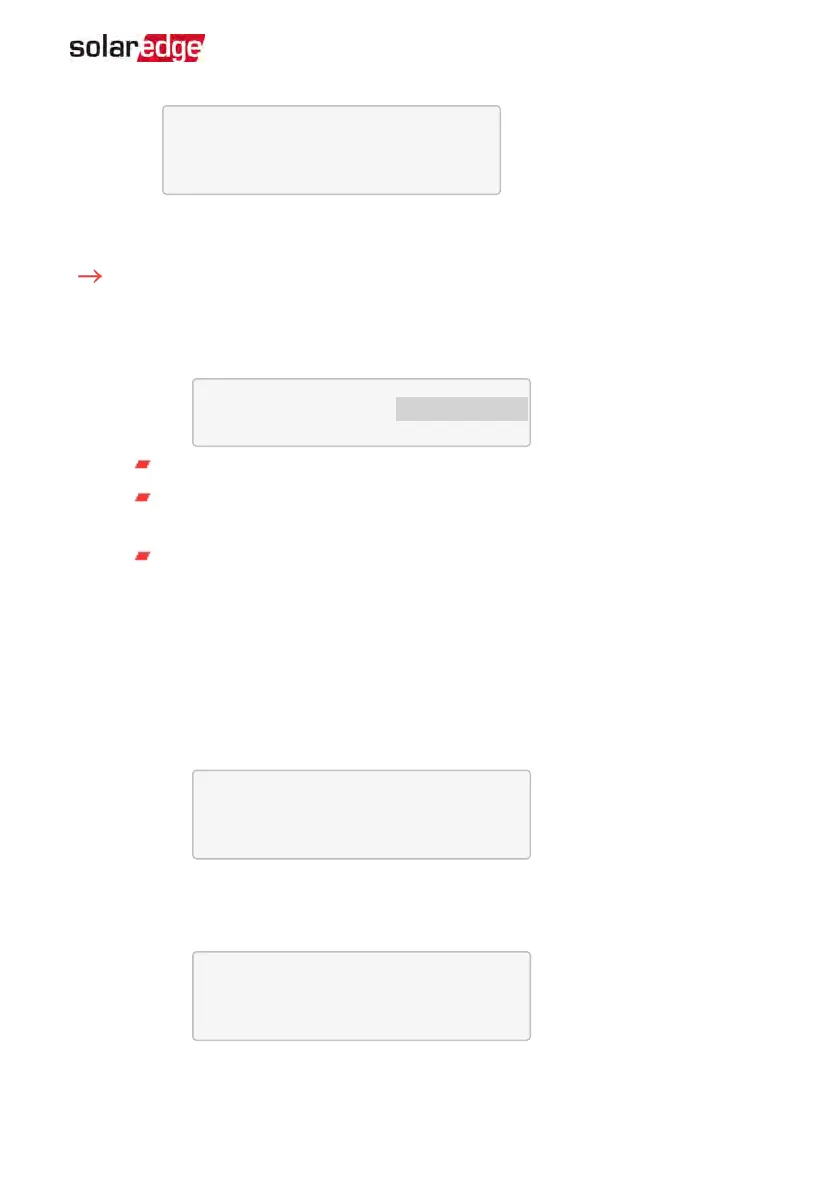
S N : < s e r i a l # >
M o d e l : < X X X X X X >
N a m e p l a t e [ k W H ] : N / A
F W V e r . < X X X X X >
Make sure to have the battery serial number and firmware version at hand whenever
contacting support.
To verify the connection:
1.
Press the inverter external LCD light button to display the status screens one after
the other:
a.
Check the RS485 communication status:
D e v P r o t # #
R S 4 8 5 - 1 < M L T > < 0 2 > < 0 2 >
The MLTunder Dev denotes that the configuration is for multiple devices.
The number under Prot (protocol) should display the number of
configured
devices.
The number under ## should display the number of
detected
devices.
The above screen shows an example of 2 devices on the same bus (for example:
meter and battery). If RGM is pre-installed, and a battery and an external meter
are also installed, the screen should show <3><3>.
If the number of devices under Prot does not match the number under ##, refer
to
Troubleshooting
on page 123.
b.
Check the meter(s): In the meter(s) status screen check that the status is OK. The
following is an example of the status of an Export (or Export+Import) meter:
E x p o r t M e t e r
S t a t u s : < O K / E r r o r # >
P o w e r [ W ] : x x x x x . x
E n e r g y [ W h ] : x x x x x . x
If Comm. Error appears, refer to
Troubleshooting
on page 123.
c.
Check the battery information: identification, charging status and power, and
the operating mode.
B S N : X X X X X X X X X I D : 1 5
S O E : 8 9 % P W R : 2 W
T o t a l : < x > W h
S t a t e : C h a r g i n g
If Comm. Error appears, refer to
Troubleshooting
on page 123.
Chapter 10: System Configuration 113
StorEdge Solution with Backup MAN-01-00262-1.5