55
en
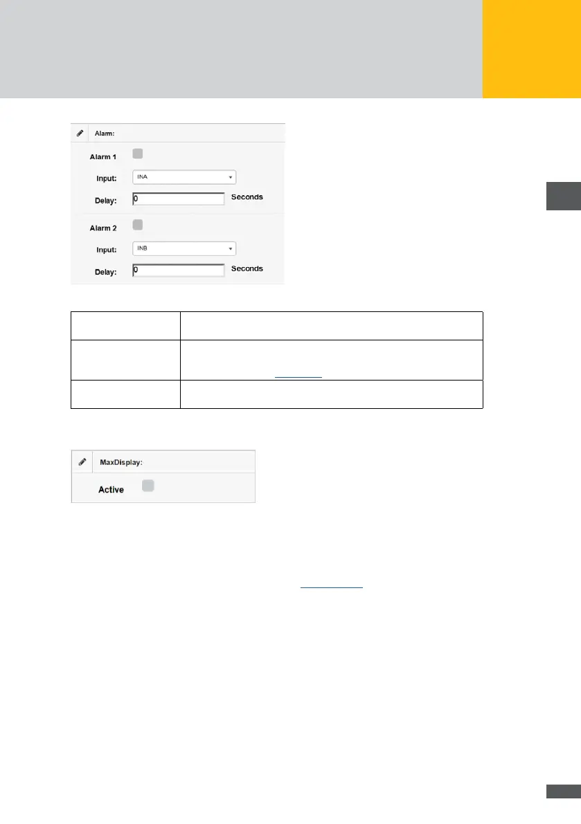
Fig. 52: Conguration of external alarm transmitters
Alarm 1 / 2: Tick this option if you have connected external alarm sensors the data
of which is to be logged.
Input:
Select the terminals to which the external alarm sensor is connected
in this menu. For a detailed overview of the assignment and designa-
tion of terminals, see Section 8.5.
Delay: In this menu, enter the number of seconds by which the signal must
be delayed for an alarm to be triggered.
If a MaxDisplay is connected, mark the “Active” checkbox in the “MaxDisplay” menu.
Fig. 53: Activation of the MaxDisplay
The operator can connect devices by using the relay outputs of the MaxWeb XPN which
can be operated with 30V/1A. These devices will be connected to the upper terminal
clamps on the rear side of the MaxWeb XPN (see Section 8.5.2).