Electrical Installation 7828 Density Transmitter Technical Manual
3-10 78285000_AB
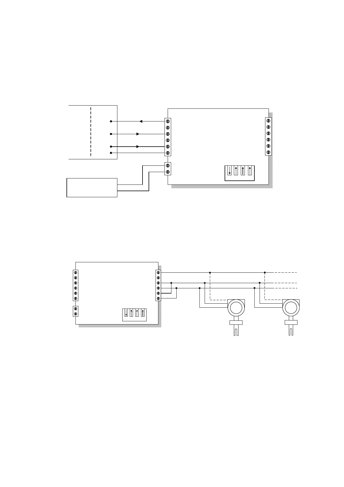
The switch on the KD485-ADE should be set with SW1 On (to enable half-duplex
operation on Port 2), with the other three switches (SW2, 3, 4) set to Off.
Connections to the RS232 port (Port 1) are shown below:
-
KD485-ADE
Tx
Rx
RTS In
Port 1 GND
Power Input
1
2
3
4
5
6
7
8
PC Connector
DB9
DB25
32
23
47
75
Power Supply
7 to 35V DC
Tx
Rx
RTS
GND
+
-
+
Port 1
RS232
6
5
4
3
2
1
RxB
Port 2 GND
RxA
TxA
TxB
Note: For a PC running Windows NT, the RTS connection can be omitted.
Connections to the RS485 port (Port 2) are:
KD485-ADE
Tx
Rx
RTS In
Port 1 GND
Power Input
1
2
3
4
5
6
7
8
-
+
6
5
4
3
2
1
Port 2
RS485
RxB
Port 2 GND
RxA
TxA
TxB
A
B
A
B
GND
GND
3
4
2
7828
A
B
GND
3
4
2
7828
Note: The ‘A’ signals on the 7828 must be connected to the ‘B’ signal on the converter,
and vice-versa.
In most systems, the ground connection will be unnecessary.
When two or more devices are connected on the same RS485 network, this is known as
a multidrop configuration (see next section). Each device must be configured with its
unique slave address before being installed on the network.