NOTE
It is recommended that the ground cable be connected to a nearby
ground position. For a system with multiple inverters connected in
parallel, connect the ground points of all inverters to ensure
equipotential connections.
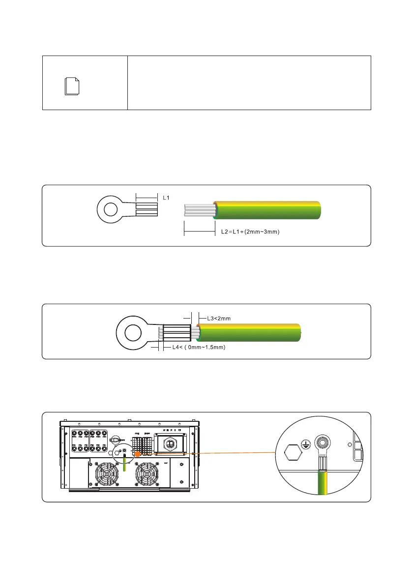
Step 1 Remove an appropriate length of the insulation layer from the PGND cable using a wire
Stripper; the length is a little bit longer than that of OT terminal’s crimping end by 2mm~3mm,
as shown in Figure 5.1.
5.1.2 Wiring Procedures
Figure 5.1 Stripped length (unit: mm)
Step 2 Insert the exposed core wires into the crimping areas of the OT terminal and crimp them
using hydraulic pliers, as shown in Figure 5.2.
Figure 5.2 Crimping a cable (unit: mm)
Step 3 ,Secure the PGND cable using the ground screw and tighten the screw to a torque of 3 N·m
as shown in Figure 5.3.
Figure 5.3 Securing the PGND cable
20

 Loading...


