31
5 4 2 Connecting RS485 Communications Cables. .
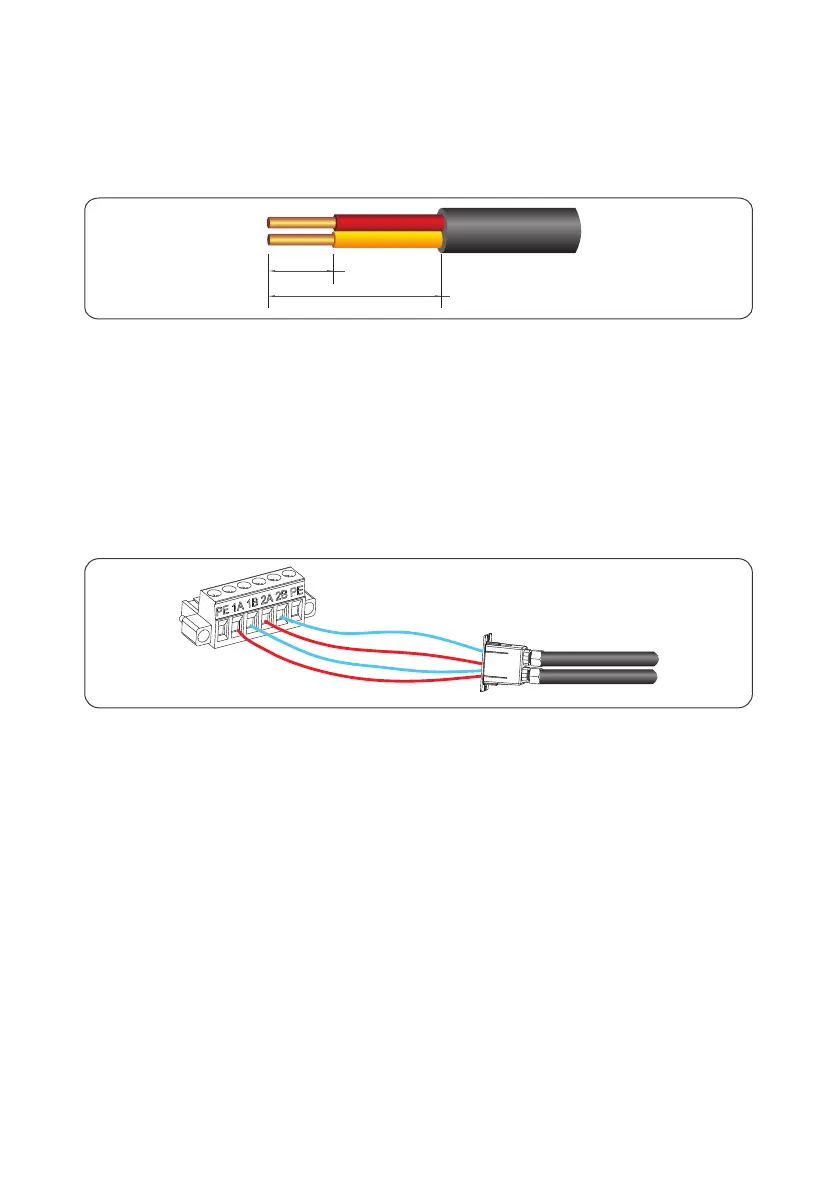
Remove an appropriate length of the insulation layer from the cable using a wire
stripper, as shown in Figure 5.18.
Remove the RS485 screws at the inverter bottom to remove the metal plate.
Take RS485 cable out of accessory kit, and remove the locking caps from the 485 IN
and 485 OUT waterproof cable connectors. Route RS485 cables through waterproof
cable connectors and reserve appreciate wire length for wiring to the inverter.
Step 1
Step 2
Step 3
≤60mm
8mm
Connect RS485 differential positive and negative signal of data logger to terminal 1A
and 1B of inverter, and connect terminal 2A and 2B of the inverter to terminal 1A and
1B of another inverter. Figure 5.19.
Step 4
Figure 5 18 Stripping an RS485 communications cable (unit: mm).
Figure 5 19 RS485 Terminal block connection.

 Loading...


