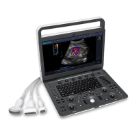
S6 Portable Digital Color Doppler Ultrasound System
Service Manual
Chapter 5
S6 Disassembly Instructions
This chapter contains step-by-step instructions on how to disassemble the
S6 system for servicing. The flowchart (Figure 5.1, page 5-2) gives a
graphic representation on the disassembly sequence and instructs the units
that need to be removed during servicing. Additionally you can find infor-
mation on connecting different parts inside the system in chapter 6.
Refer to table on page 4-5 to find the part numbers of the PCB
boards.
Refer to the contents table on page 6-1 to find the part num-
bers of the wires/cables .
Connector identification numbers, normally in the form of ‘J#’,
are marked on the corresponding PCB boards. Connectors
on the motherboard are indicated in figure 6.1 on page 6-3.
It is recommended to follow procedures in the flowchart to re-
place the faulty component.
Contents
5.1 Bottom Cover . . . . . . . . . . . . . . . . . . . . . . . . . . . . 5-3
5.2 Back Cover . . . . . . . . . . . . . . . . . . . . . . . . . . . . . . 5-4
5.3 Motherboard . . . . . . . . . . . . . . . . . . . . . . . . . . . . . 5-6
5.4 KEAA board . . . . . . . . . . . . . . . . . . . . . . . . . . . . . 5-7
5.5 HDD . . . . . . . . . . . . . . . . . . . . . . . . . . . . . . . . . . 5-9
5.6 Voltage Conversion Board . . . . . . . . . . . . . . . . . . . . . 5-10
5.7 Fans . . . . . . . . . . . . . . . . . . . . . . . . . . . . . . . . . . 5-11
5.8 MPC board . . . . . . . . . . . . . . . . . . . . . . . . . . . . . . 5-12
5.9 Ultrasound Module Assembly . . . . . . . . . . . . . . . . . . . 5-12
5.9.1 Ultrasound Metal Shield . . . . . . . . . . . . . . . . . 5-13
5.9.2 Ultrasound Module . . . . . . . . . . . . . . . . . . . . 5-14
5.10 Power Unit . . . . . . . . . . . . . . . . . . . . . . . . . . . . . . 5-16
5.11 Keyboard Assembly . . . . . . . . . . . . . . . . . . . . . . . . . 5-17
5.12 LCD assembly . . . . . . . . . . . . . . . . . . . . . . . . . . . . 5-18
P/N: 4720-0034-01A
5-1