S6 Portable Digital Color Doppler Ultrasound System
Service Manual
Connection Instructions: Connect CN1 to XS3 on the keyboard. Connect
CN2 to the trackball (keep the white wire upwards.) Avoid inserting the
connectors by force.
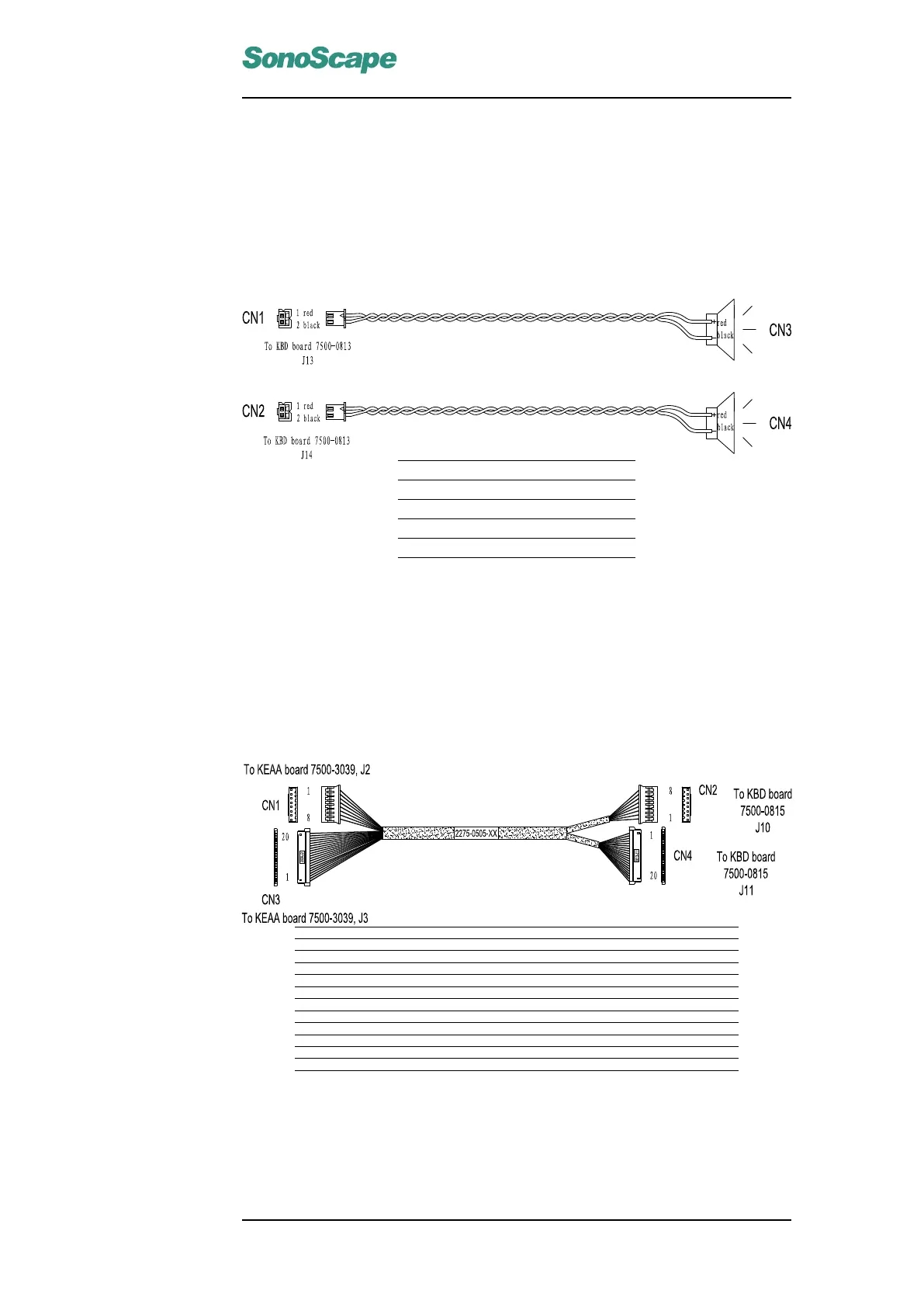
6.3.4 Connection cable for loud speakers (3520-0504)
Color Red Black Red Black
CN1 1 2
CN2 1 2
CN3 + -
CN4 + -
Connection Instructions:
Connect CN1 and CN2 to J13 and J14 respectively. Connect CN3 and CN4
to the loudspeaker sockets on the keyboard assembly.
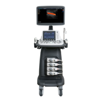
6.3.5 Signal Transmission cable for keyboard (3520-0505)
Signal VCC VCC VCC GND GND GND +12V +12V
Color Red Red Red Shield Shield Shield Yellow Yellow
CN1 1 2 3 4 5 6 7 8
CN1 1 2 3 4 5 6 7 8
Signal GND Laudio Raudio GND GND PRT CTRL PRT BUSY GND FSW1 FSW2
Color Black Blue Orange Black Black Brown White Black Green Green
CN3 1 2 3 4 5 6 7 8 9 10
CN4 1 2 3 4 5 6 7 8 9 10
Signal GND PowerSWL PowerSWR GND KBPS2DATA KBPS2CLK GND TBPS2DATA TBPS2CLK GND
Color Black Green Green Black Brown White Black Blue Orange Black
CN3 11 12 13 14 15 16 17 18 19 20
CN4 11 12 13 14 15 16 17 18 19 20
Connection Instructions:
Connect CN1 and CN3 to J2 and J3 respectively on the KEAA board. Con-
nect CN2 and CN4 to J10 and J11 respectively on the KBD board. Make
sure to attach these connectors tight.
P/N: 4720-0034-01A
6-5