S6 Portable Digital Color Doppler Ultrasound System
Service Manual
Connection Instructions:
Connect CN1 to USB2 on the motherboard. Make sure to connect in the
correct direction: the vacant hole on CN1 corresponds to the single-pin side
of USB2. Connect CN3 to the GND pin on the motherboard. Connect CN2
to the DBF board.
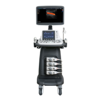
6.3.11 USB Cable for µ-Scan Dongle(3520-0511)
Signal +5V D- D+ GND N/C GND
Color red white green black no pin shield
CN1 1 3 5 7 10
CN2 1 2 3 4 Metal shell
CN3 GND pin
Connection Instructions:
Connect CN1 to USB3 on the motherboard. Make sure you get the correct
direction: the vacant hole on CN1 should correspond to the single-pin side
on USB3. Connect CN3 to ground on the motherboard. Fasten CN2 to the
motherboard bracket, and connected it to the µ-Scan Dongle.
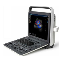
6.3.12 Power Supply Cable for Voltage Inversion Board (3520-
0512)
Signal Vcc Vcc Vcc GND GND GND
Color red red red green white black black black
CN1 1 2 3 4 5 6 7 8
CN2 8 7 6 5 4 3 2 1
Connection Instructions:
Connect CN1 to the voltage inversion board. Connect CN2 to P5 on the
DBHV board.
P/N: 4720-0034-01A
6-8