S6 Portable Digital Color Doppler Ultrasound System
Service Manual
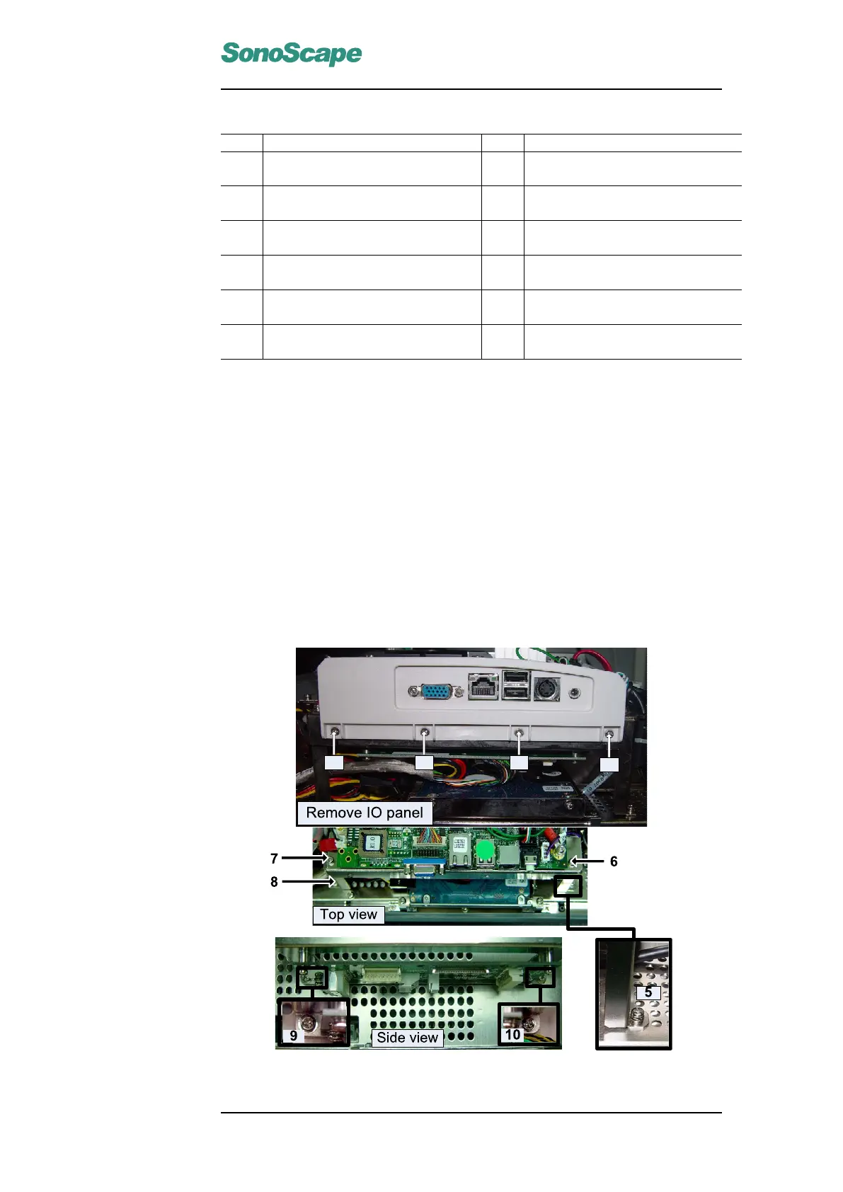
Item Description Item Description
1 HDD SATA cable (3520-0506) →
SATA1
2 Keyboard cable (3520-0508, CN2)
→EKBM1
3 USB cable shield 4 Audio cable (3520-0508, CN4) →
SOUT1
5 USB cable for DBF board
(3520-0510) → USB2
6 USB cable for µ-SCAN dongle
(3520-0511) → USB3
7 LVDS cable (3520-0507) → JC2 8 Composite video BNC cable
(3520-0515) → JC3
9 LVDS shield 10 Power cable for CPU (for connection
refer to Sec. 6.3.16)
11 Power cables for motherboard (for
connection refer to Sec. 6.3.16
12 Power switch wires (3520-0508,
CN3) → J3
Instructions
Disconnect all the cables shown in the picture.
Remove the four screws fastening the motherboard.
Note for installation:
The two USB wires (5∼6) should be connected in the correct order.
Refer to chapter 6 and the schematic diagram in appendix B to connect power
cables/wires.
5.4 KEAA board
Figure 5.3: KEAA Board
P/N: 4720-0034-01A
5-7