S6 Portable Digital Color Doppler Ultrasound System
Service Manual
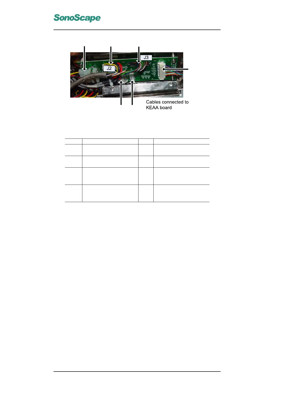
Figure 5.4: Cables Connected to KEAA Board
Item Description Item Description
1∼4 Countersunk head screws
M3×6
5∼10 Combination screws M3×6
11, 16 Keyboard data cables
(3520-0505) → J2 & J3
12 KEAA main cables (3520-
0508) → XS2
13 Power wires for fans
(3520-0509) → J1
14 Foot switch and video
printer control cables
(5320-0514) → XS3
15 Power wires for KEAA
board (refer to Sec.
6.3.16) → XS1
Instructions
Remove the four screws (1∼4), and remove the plastic IO panel.
Remove the four screws (5∼8). Note that screws 5 and 8 are at symmetrical
positions.
Disconnect the wires 9∼14, and remove the KEAA board together with the
metal frame.
P/N: 4720-0034-01A
5-8