S6 Portable Digital Color Doppler Ultrasound System
Service Manual
9.3.2.1 HP K5400DN Installation Procedures
8 Printheads
9 Printhead latch
10 Top cover
Control panel
For more information about interpreting control-panel lights, see Control-panel lights
reference.
1 Ink cartridge lights
2 Printhead lights
3 Configuration Page button (available with some models)
4 Cancel button
5 Resume button and light
6 Power button and light
Back view
1 Power input
2 Ethernet network port (available with some models)
3 Rear universal serial bus (USB) port
4 Rear access panel (for models with no duplexer)
5 Automatic two-sided printing accessory (duplexer) (available on some models)
Chapter 1
(continued)
8 Get started
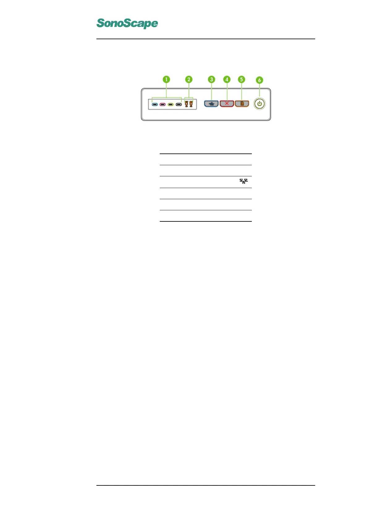
Figure 9.1: HP K5400DN Control Panel
1 Ink cartridge lights
2 Printhead lights
3 Configuration Page button
S8 Portable Digital Color Doppler Ultrasound System
Service Manual
HP K5400dn Installation Procedures
8 Printheads
9 Printhead latch
10 Top cover
Control panel
For more information about interpreting control-panel lights, see Control-panel lights
reference.
1 Ink cartridge lights
2 Printhead lights
3 Configuration Page button (available with some models)
4 Cancel button
5 Resume button and light
6 Power button and light
Back view
1 Power input
2 Ethernet network port (available with some models)
3 Rear universal serial bus (USB) port
4 Rear access panel (for models with no duplexer)
5 Automatic two-sided printing accessory (duplexer) (available on some models)
Chapter 1
(continued)
8 Get started
1. Install printer driver on the computer.
2. Connect the printer to the computer with an Ethernet cable. Turn the
printer on and wait for a while (about 3 minutes), press Configuration
Page button on the printer, the printer information together with its cur-
rent IP address (allocated randomly) will be printed out. (See below) In
this example the IP address is 169.254.103.148.
P/N 4720-0020
8-3
4 Cancel button
5 Resume button and light
6 Power button and light
1. Install printer driver on the computer.
2. Connect the printer to the computer with an Ethernet cable. Turn the
printer on and wait for a while (about 3 minutes), press Configuration
Page button on the printer, the printer information together with its
current IP address (allocated randomly) will be printed out. (Refer to
figure on page 9-4) In this example the IP address is 169.254.103.148.
3. Change this randomly allocated IP address to a fixed address,
192.168.254.183, by following these steps (also refer to figure 9.3),
(a) Set the computer’s IP address to 169.254.103.55.
(b) Type the IP address printed out in step 2, i.e., 169.254.103.148
in our example, into the address bar of the IE explorer and press
the Enter key. This leads to the printer setting page.
(c) Click "Connection" on top left of the window, and then click
"Wired",
(d) Select "Manual IP Address". Set the IP address to 192.168.254.183,
and the manual subnet mask to 255.255.255.0.
P/N: 4720-0034-01A
9-3