30
Output circuit
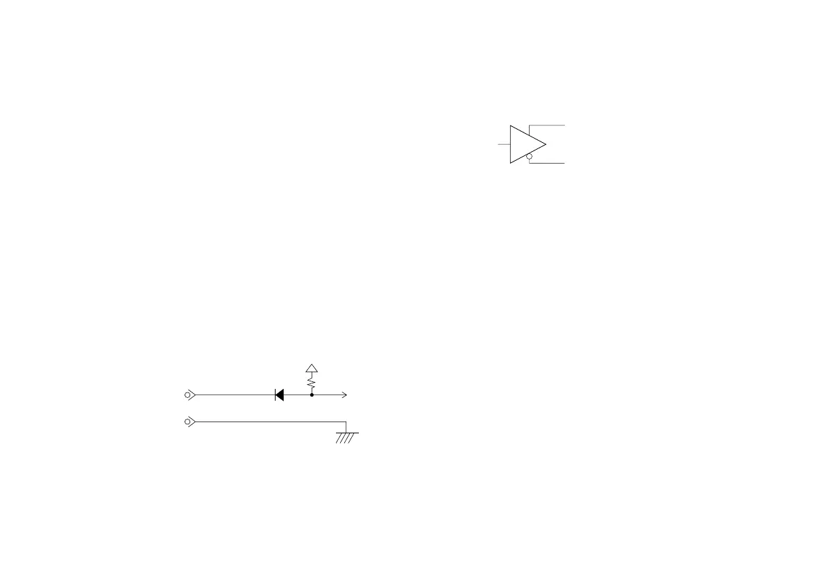
Voltage-differential drivers (SN75113) are used to
produce outputs. Therefore use voltage-differential
line receivers (SN75115 or equivalent) to receive
those outputs.
Power requirements
DC +5 V (±5%)
Power consumption
2 W (Max.)
Operating temperature range
0 to +45 °C/32 to 113 °F
Storage temperature range
−10 to +50 °C/14 to 122 °F
Head cable length
10 m (PL23-AF), 3 m (PL23-3F)
Total weight PL23-AF: 1030 g/2.318 lb
PL23-3F : 620 g/1.395 lb
Accessories Head installation screws (M4×20) ............... 2 pcs.
Detector installation screws (M4×10) .......... 4 pcs.
Cable clamp screws (M4×8) ........................ 3 pcs.
Techinical Information ................................... 1 pc.
Output connector ........................................... 1 set
Instruction manual ......................................... 1 pc.
Cable clamps ............................................... 3 pcs.
Spacer ............................................................ 1 pc.
Reference point accuracy
1 pulse/4 pulses (selectable)
Ex. : When the resolution is set to 10 µm, the accuracy
is selectable between 10 µm and 40 µm.
Signals PCA, PCB, PCZ and ALARM
Signals *PCA, *PCB, *PCZ and *ALARM
Alarm signal If the scale exceeds the maximum response speed
or if a head cable connection becomes open, an
alarm is triggered. When an alarm is triggered, the
ALARM output goes high (the *ALARM output goes
LOW). At this time, the output signal except the
reference point assumes high impedance state.
Alarm clearing
To reset the alarm, remove all the causes of the
alarm and perform a reset or remove power and
apply power once again.
With the alarm triggered, if the external reset is
begin applied, the alarm signal will not be output
and outputs will not go into the high-impedance
state. However, the output signals will be stopped.
Reset To perform a reset, short pins 20 and 7 of the output
connector.
External reset signal input
Maximum reset time: 300 ms
Maximum short-circuit current: 0.5 mA
Maximum operation reset time: 10 ms
(after the reset is canceled)
External reset signal input circut
P20:RES
P7:GND