21
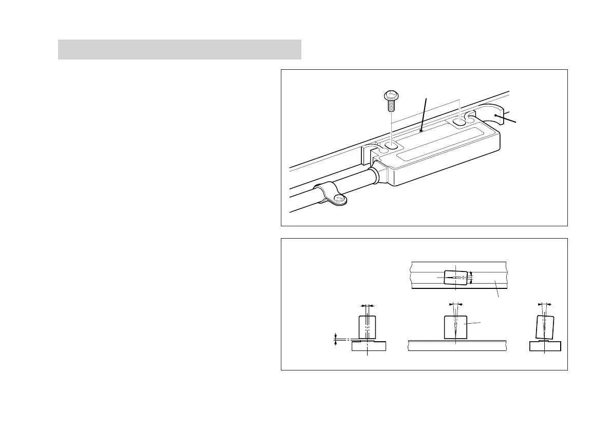
3-2. Head Installation
The detection sensor is built into head where it is
marked with “∇”. Install the head so that the “∇”
mark is always within the measuring length of the
scale.
• To fasten the head, insert the accessory spacer
between the detection surface of the head and the
scale, and install with the accessory screws (M4 × 20).
• After installing the head, remove the spacer.
• Tightening torque should be 0.7 N·m (7 kg·cm) to
1.1 N·m (11 kg·cm).
• After installing the head, use the accessory cable
clamps to fasten the cable where it extends from
the head. Make sure the cable is not loose.
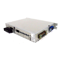
• The relative positions of the scale and head should
be as shown in Fig. 3-2.
“∇” mark
Spacer
±2mm
<
θ
2
θ
1
±
0.5
<
θ
1
±
3
〇
<
θ
3
±
3
〇
〇
Head
Scale surface
±2 mm/±0.08"
Fig. 3-2
Clearance
1.5 mm/0.06"
(Max.)