5-37
DSC-P31/P31M
Processing after Completing Adjustments:
Order Page Address Data Procedure
1A 02 00 Press PAUSE button.
24 F100
30 0100
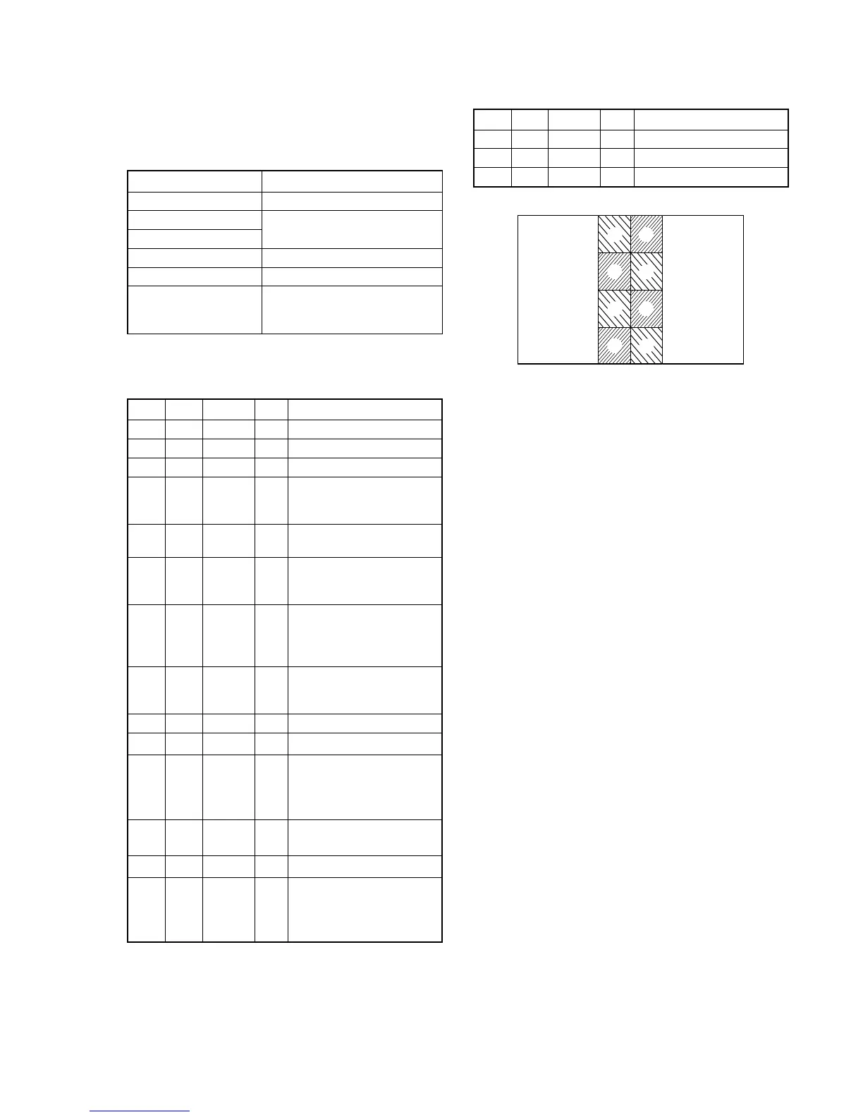
7. V-COM DC Adjustment (PK-062 Board)
Set the DC bias of the common electrode drive signal of LCD to
the specified value.
If deviated, the LCD display will be move, producing flicker and
conspicuous vertical lines.
Mode PLAY
Signal Arbitrary
Measurement Point
Check on the LCD screen
Measuring Instrument
Adjustment Page A
Adjustment Address 84
Specified Value Shake the set from side to side
and check that no stripe lines can
be seen in the blue back image.
Note 1: Perform “Bright Adjustment” and “Contrast Adjustment”
before this adjustment.
Adjusting method:
Order Page Address Data Procedure
10 0101
2A 02 03 Press PAUSE button.
34 F182
4A 84
Change the data so that
brightness of the section A
and section B is equal.
5A 84
Read the data and this data is
named Dref.
6
Convert Dref to decimal
notation, and obtain Dref’.
(Note 2)
7
Calculate D
84
’ using
following equations.
(decimal calculation)
D
84
’ = Dref’ – 10
8
Convert D
84
’ to a hexadeci-
mal number, and obtain D
84
.
(Note 2)
9A 84D
84
Press PAUSE button.
10 4 F1 07
11
Shake the set from side to
side and check that no stripe
lines can be seen on the LCD
screen. (Note 3)
12 A 84 Subtract 08 from the adjust-
ment value (D
84
) (Note 2)
13 A 84 Press PAUSE button.
14
Shake the set from side to
side and check that no stripe
lines can be seen on the LCD
screen. (Note 4)
Note 2: Refer to table 5-2-2. “Hexadecimal-decimal conversion
table”.
Note 3: When any stripe lines are seen, perform the following
precedure.
Note 4: If any suitable value can not be found, input the value of
D
84
and finish this adjustment.
Fig. 5-1-21
A
A
A
A
B
B
B
B