1-9
DSR-45/45P
Chapter 2 Playback and Recording
41
(GB)
Chapter 2 Playback and Recording
Recording
This section describes the connections, settings and
operations necessary to perform recording on this unit.
The same settings and operations apply whether you
are using the unit for dubbing or as a stand-alone
recorder.
Connections for Recording
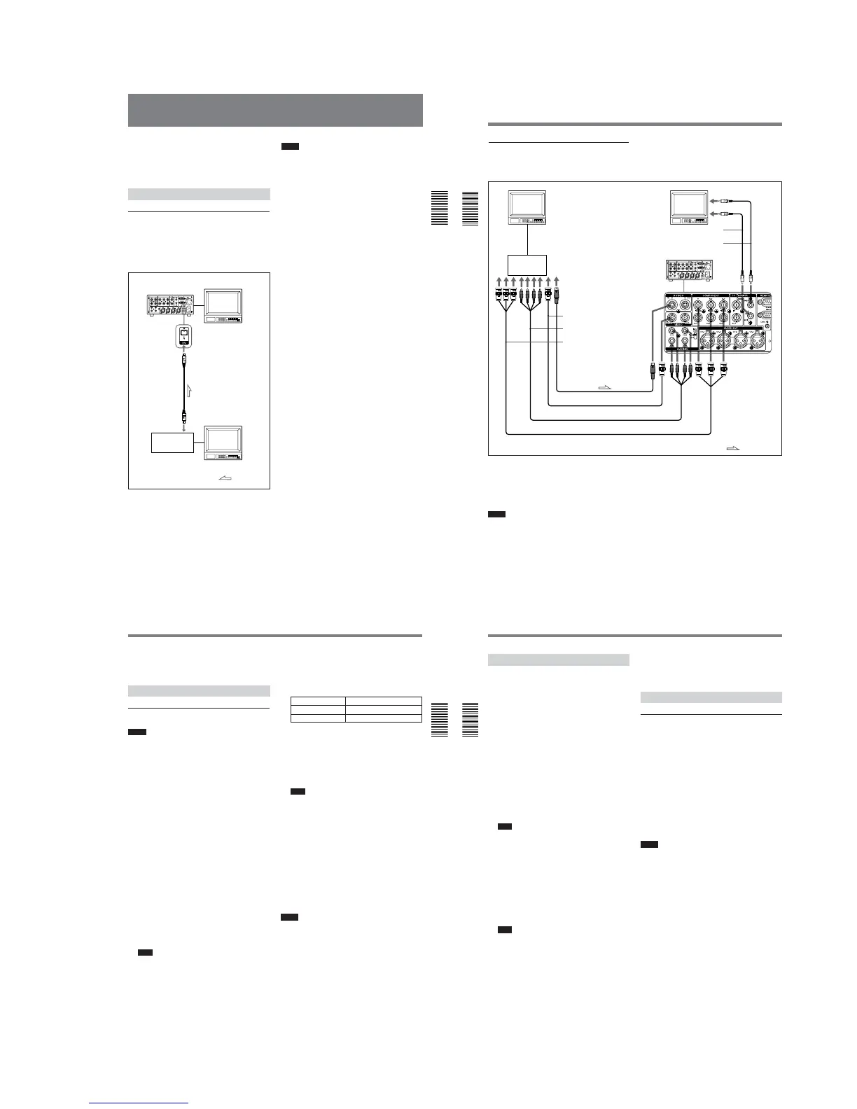
To digital video equipment with a DV jack
The video and audio signals are sent with hardly any
degradation, enabling high-quality recording. The
signal flow is automatically detected so you do not
need to make separate connections for input and
output.
Notes
•With the DV connection, the sound is recorded in the
same audio recording mode as that of the source tape.
To record in a different audio recording mode from
the source tape, use the analog connection instead.
•With the DV connection, data codes (recording date/
time, camera data) recorded on the source tape are
transmitted to the recorder (this unit). As a result,
when you play back a recorded tape on this unit and
press the DATA CODE button on the Remote
Commander, the same data codes as those recorded
on the source tape are displayed on the monitor
screen. However, the contents of the cassette memory
are not transmitted. If you want to transmit the
contents of the cassette memory, use the duplicate
function.
•If no picture appears via the DV jack, disconnect the
i.LINK cable (DV cable), then reinsert it straight.
•When connecting a device that has a 6-pin DV jack to
this unit, first, connect the plug of the cable to the 6-
pin DV jack.
•If the unit is connected to a device equipped with a 6-
pin DV jack, when you intend to disconnect or
reconnect the DV cable, turn off the device and pull
out the plug of its power cord from the AC outlet
beforehand. If you connect or disconnect the DV
cable while the device is connected to the AC outlet,
high-voltage current (8 to 40 V) is output from the
DV jack of the device to this unit, which may cause a
malfunction.
•If you connect the output connectors of this unit to
the input connectors of a player or that of a monitor, a
humming noise may be generated or the image may
be distorted. If these phenomena occur, perform one
of the following:
– Set DV EE OUT on the VTR SET menu to OFF.
– Set the INPUT SELECT selector to a position
where a signal is not currently being input.
–Disconnect the cables.
DSR-45/45P (rear panel)
Monitor
i.LINK cable
(DV cable)
(not supplied)
DV jack
Digital video
equipment with a
DV jack
: Signal flow
Monitor
42
(GB) Chapter 2 Playback and Recording
Chapter 2 Playback and Recording
Recording
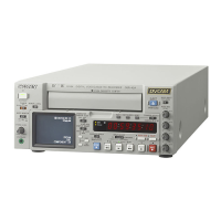
To video equipment without a DV jack
You can connect this unit to video equipment without
a DV jack. Use this unit as a recorder as follows.
Connect one of the following as a video cable: video
cable (3BNC y 3BNC), S-video cable, or 75 Ω
coaxial cable.
Use a conversion cable for the audio connection,
depending on types of audio output connectors on the
player (see page on 23 (GB)).
Notes
•During recording, analog input signals can be output
simultaneously from the DV jack for backup. Set DV
EE OUT on the VTR SET menu to ON.
For details on the VTR SET menu, see “VTR SET menu”
on page 90 (GB).
•If you connect the output connectors of this unit to
the input connectors of the player, a humming noise
may be generated or the image may be distorted. If
these phenomena occur, set the INPUT SELECT
selector to a position where a signal is not currently
being input, or disconnect the cables.
Monitor
Monitor
Phono jack cable
(not supplied)
Audio input
Video input
DSR-45/45P (recorder)
(rear panel)
Phono
jack cable
(not
supplied)
Player
S-video output
Video output
Audio output
Component output
S-video cable (not supplied)
75 Ω coaxial cable (not supplied)
Audio cable (phono jack) (not supplied)
Video cable (3BNC y 3BNC) (not supplied)
: Signal flow
Chapter 2 Playback and Recording
43
(GB)
Chapter 2 Playback and Recording
•Distorted signals (e.g., when played back at a speed
other than normal) may not be recorded or may be
distorted.
Settings for Recording
Preparation on the recorder (this unit)
Notes
•Before recording, set the date and time on the unit so
that the recording time can be written into the search
signal. You can set the date and time by setting
CLOCK SET on the OTHERS menu.
For details on the OTHERS menu, see “OTHERS menu”
on page 92 (GB).
•Editing may not be possible with a signal that is
copyright protected.
1
Power on the video monitor, then set the monitor’s
input according to the input signals.
2
Set up the player to play back a tape.
For details, refer to the instruction manual of the
player.
3
Turn this unit on.
4
Select an input signal by switching the INPUT
SELECT selector on this unit.
DV: to record input signals from the DV jack
S VIDEO: to record input signals from the S
VIDEO IN connector
VIDEO: to record input signals from the VIDEO
IN REF.IN connector
COMPONENT: to record input signals from the
COMPONENT IN connector
Note
Do not change the selector setting during
recording. Otherwise, noise is output to the picture
and sound and that portion will not be recorded
properly.
5
Select the audio mode. (With a DV connection,
skip this step.)
Select the desired mode by setting AUDIO MODE
on the AUDIO SET menu.
Audio mode Set the menu to
4-channel mode FS32K
2-channel mode FS48K
For details on the AUDIO SET menu, see “AUDIO SET
menu” on page 88 (GB).
6
Set the INPUT LEVEL selector on the rear panel
properly according to the audio level of the player.
7
Select the audio recording level adjustment mode
using the AUDIO INPUT switch.
Note
You cannot adjust the recording level if you record
signals input via the DV jack.
8
If necessary, adjust the audio recording level by
turning the AUDIO REC LEVEL control knobs.
You can adjust the recording level with the
AUDIO REC LEVEL control knobs if you have
selected MANU in step 7. While looking at the
audio level meters on the LCD monitor, turn the
AUDIO REC LEVEL control knobs to adjust the
recording level. Adjust the audio recording level so
that it does not exceed 0 dB when the audio signal
is at its maximum. If the recording level exceeds
0 dB, the recorded sound will be distorted.
Notes
•In the DVCAM format, there are two audio modes,
with either two channels at FS48K or four channels at
FS32K. It is not possible to select other modes (for
example with two channels at FS32K).
• During recording, you cannot change the audio mode.
• If you intend to dub a sound on the tape after it has
been recorded, set AUDIO MODE on the AUDIO
SET menu to FS32K (4-channel mode) before
recording.
For details on the AUDIO SET menu, see “AUDIO SET
menu” on page 88 (GB).
44
(GB) Chapter 2 Playback and Recording
Chapter 2 Playback and Recording
Recording
Recording Procedures
This section describes the procedures used to record
signals sent from another VCR to this unit. For details
on the procedures required when using a computer as a
player, refer to the instruction manual of your
computer or the user’s manuals of the software
installed on it.
1
After checking that the REC/SAVE switch on the
cassette is set to REC, checking the tape for slack
and confirming that the q indicator is off, hold
the cassette so that the tape window is facing
upward, then insert it into this unit.
The cassette is automatically loaded into the unit
and the tape will be ready to record.
For details on the REC/SAVE switch and checking the
tape for slack, see “Notes on Video Cassettes” on page
30 (GB).
For details on inserting a cassette, see “To insert a
cassette” on page 31 (GB).
Note
Do not insert the cassette forcibly. The unit may be
damaged.
2
Press the playback button on the player.
The player starts playback.
3
On this unit, press the PLAY button while holding
the REC button down.
The unit starts recording. If AUTO INDEX on the
VTR SET menu is set to ON, the index is marked.
Note
When you do not want to mark an index at the
beginning of the recording, set AUTO INDEX on
the VTR SET menu to OFF.
For details on the VTR SET menu, see “VTR SET
menu” on page 90 (GB).
To stop recording
Press the STOP button on this unit.
To pause recording
Press the PAUSE button on this unit.
To start recording using the Remote Control
Unit (DSRM-20, not supplied)
On the Remote Control Unit, press the PLAY button
while holding the REC button down.
Recording Functions
Marking an index
By pressing the INDEX button on the unit or the
INDEX WRITE button on the Remote Commander
during recording, you can mark an index signal at any
place on the tape. The index signal is inserted for five
seconds. If you mark an index at the scene you want to
search for, you can easily find the scene later.
If AUTO INDEX on the VTR SET menu is set to ON,
the index signal is marked automatically when the unit
in the stop mode starts recording.
While the index is being marked, the “INDEX
MARK” indicator appears for about seven seconds on
the Data screen (see page 27 (GB)).
If you use a cassette with cassette memory, the index
will also be marked in the cassette memory.
Notes
•You cannot mark a new index while the “INDEX
MARK” indicator is being displayed.
•If you record on a portion of the tape where an index
has been marked, the index will be erased. You
cannot delete just an index while keeping the image
or sound.
•You cannot mark an index during playback,
duplicating or audio dubbing operations. The INDEX
button and the INDEX WRITE button are disabled in
these operations.
•The cassette memory space available limits the
number of indexes that you can mark. When you use
a previously recorded tape for repeated recordings,
make more memory space available by erasing
unwanted items using ITEM ERASE or ERASE ALL
on the CM SET menu before you start recording.
To use an index during playback
You will need the Remote Commander or the Remote
Control Unit (DSRM-20, not supplied).
For details on the playback functions using the Remote
Commander, see “Searching using the search function” in
“Playback Functions” on page 37 (GB).


 To Next Page