5-91
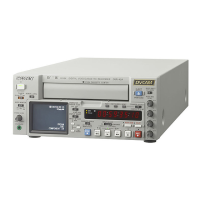
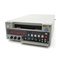
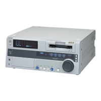
DSR-45/45P
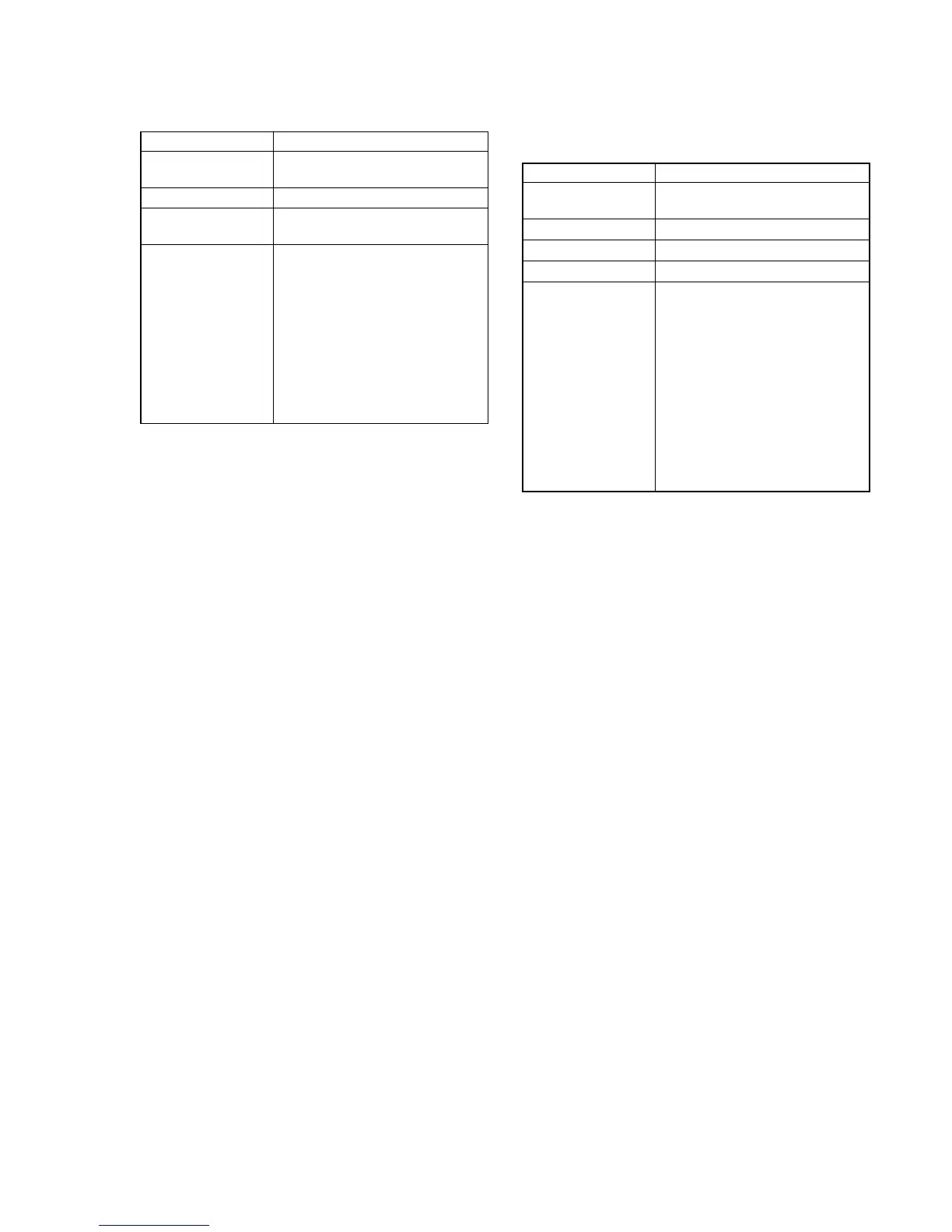
2. Playing Level Check
Mode PLAY
Signal Alignment tape: For audio check
(NTSC: XH5-3/PAL: XH5-3P)
Measurement Point AUDIO OUT terminal (CH-1, 2)
Measuring instrument Audio level meter
Oscilloscope
Specified Value 32 kHz mode section:
1 kHz signal must be outputted.
48 kHz mode section:
1 kHz signal level is +22 to +26
dBu.
44.1 kHz mode EMP ON section:
7.35 kHz signal level is +16 to
+20 dBu.
44.1 kHz mode EMP OFF section:
7.35 kHz signal level is +22 to
+26 dBu.
Note: 0 dBu = 0.775 Vrms/balance
Checking method:
1) Check that the play signal level satisfies the specified value.
2) Check with the oscilloscope that no clip is found in the output
waveform.
3. E-E Level Check
(1) -10dB Check
Mode STOP
Signal Audio: 1 kHz, –10 dBs signal
AUDIO IN terminal (CH-1 to 4)
Measurement Point AUDIO OUT terminal (CH-1 to 4)
AUDIO MONITOR OUT terminal
Measuring instrument Audio level meter
Specified Value At max. REC LEVEL:
+13 to +19 dBu
At min. REC LEVEL:
No signal is present.
At –20 dB displayed on FINE screen
with rotating the AUDIO REC
LEVEL control knob:
Control knob position ±30 deg.
of center
AUDIO OUT terminal
+2 to +6 dBu
AUDIO MONITOR OUT terminal
–25 to –19 dBs
Note 1: 0 dBu = 0.775 Vrms/balance
Note 2: 0 dBs = 0.775 Vrms
Switch setting
INPUT LEVEL select switch .......................... –10
Menu setting (AUDIO SET menu)
AUDIO MODE ................................................FS32K
Checking method:
1) Enter 1 kHz, –10 dBs signal to the AUDIO IN terminal (CH-
1).
2) Check that the output of AUDIO OUT terminal (CH-1) satis-
fies the specified value, when the AUDIO REC LEVEL con-
trol knob (CH-1) on the front panel is in the maximum posi-
tion.
3) Check that the output of AUDIO OUT terminal (CH-1) satis-
fies the specified value, when the AUDIO REC LEVEL con-
trol knob (CH-1) is in the minimum position.
4) Press the “FINE” button on the front panel to display the au-
dio level of LCD monitor on the FINE screen.
5) Adjust the AUDIO REC LEVEL control knob (CH-1) so that
the FINE screen on CH-1 displays “–20”.
Note 3: Unless otherwise specified, do not rotate the AUDIO
REC LEVEL control knob, as other checking items
use this setting (rotation angle) of the AUDIO REC
LEVEL control knob.
6) Check at this time that the control knob position, AUDIO OUT
terminal (CH-1) output, and AUDIO MONITOR OUT termi-
nal output satisfy the specified values. (Audio signal is input
only to CH-1)
7) For the CH-2 to 4, make a checking in the same manner.
When CH-3 or CH-4 is checked, set the AUDIO MONITOR
select switch to “CH3/4”.


 To Next Page