5-84
DSR-45/45P
3-5. LCD SYSTEM ADJUSTMENTS
Note 1: The back light (fluorescent tube) is driven by high volt-
age AC power supply. Therefore, do not touch the back
light holder to avoid electrical shock.
Note 2: When replacing the LCD unit, be careful to prevent dam-
ages caused by static electricity.
Note 3: Adjust the LCD BRIGHT and LCD COLOR to the cen-
ter on menu display.
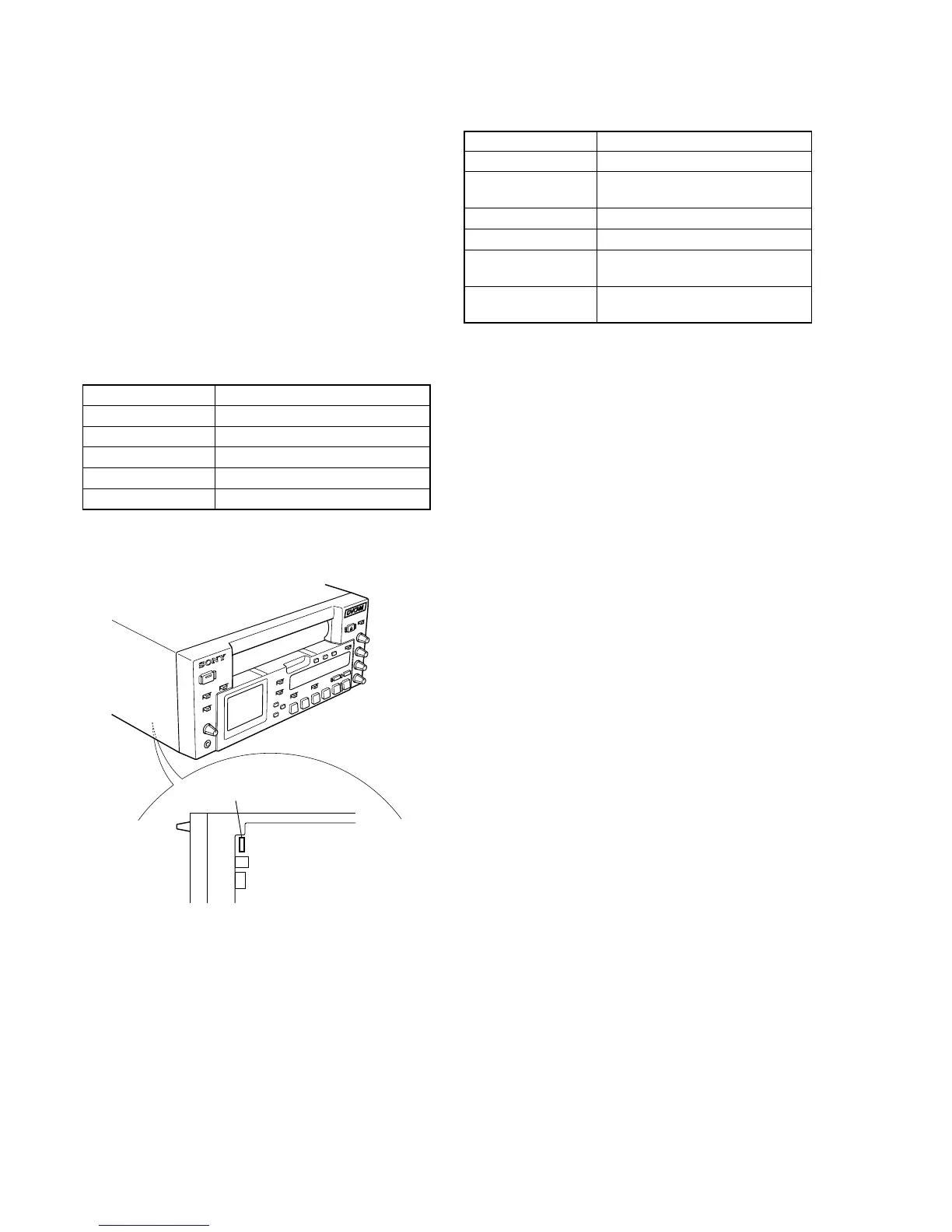
[Adjusting connector]
Most of the measuring points for adjusting the LCD are concen-
trated in the CN1504 of VD-032 board.
The following table shows the Pin No. and signal name of the
CN1504.
Pin No. Signal Name
1 N. C.
2 GND
3PANEL_COM
4 HSY
5VG
Fig. 5-3-46
1. VCO Adjustment (PD-170 Board)
Mode E-E
Signal Arbitrary
Measurement Point Pin 4 of CN1504 on VD-032 board
(HSY)
Measuring Instrument Frequency counter
Adjustment Page E
Adjustment Address 87 (NTSC)
8C (PAL)
Specified Value f = 15734 ± 30 Hz (NTSC)
f = 15745 ± 30 Hz (PAL)
Adjusting method:
1) Select page: 0, address: 01, and set data: 01.
2) Select page: 3, address: 0C, set data: 60, and press the PAUSE
button of the adjustment remote commander.
3) Select page: 3, address: 22, set data: 03, and press the PAUSE
button.
4) Select page: E, address: 87 (NTSC) or 8C (PAL), change the
data and adjust the VCO frequency (f) to the specified value.
5) Press the PAUSE button of the adjustment remote commander.
6) Select page: 3, address: 22, set data: 00, and press the PAUSE
button.
7) Select page: 3, address: 0C, set data: 00, and press the PAUSE
button.
8) Select page: 0, address: 01, and set data: 00.
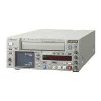
CN1504
VD-032 board


 To Next Page