5-69
DSR-45/45P
A
H
A
H
A
H
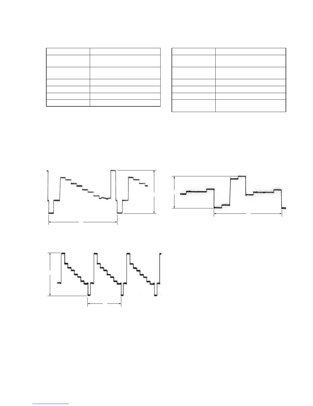
22. Component E-E Y Signal Level Adjustment
(VD-032 Board)
Mode E-E
Signal Color bar (COMPONENT input)
(Note)
Measurement Point COMPONENT OUT Y terminal
(75 Ω terminated)
Measuring Instrument Oscilloscope
Adjustment Page E
Adjustment Address 94
Specified Value A = 1000 ± 10 mVp-p
Note: Set “COMPONENT” mode with INPUT SELECT switch
Adjusting method:
1) Select page: 0, address: 01, and set data: 01.
2) Select page: E, address: 94, change the data and adjust the
component Y signal level (A) to the specified value.
3) Press the PAUSE button of the adjustment remote commander.
4) Select page: 0, address: 01, and set data: 00.
Fig. 5-3-28
For PAL model
For NTSC model
23. Component E-E CR Signal Level Adjustment
(VD-032 Board)
Mode E-E
Signal Color bar (NTSC: with 7.5% setup)
(COMPONENT input) (Note)
Measurement Point COMPONENT OUT R-Y terminal
(75 Ω terminated)
Measuring Instrument Oscilloscope
Adjustment Page E
Adjustment Address 96
Specified Value A = 700 ± 10 mVp-p (NTSC)
A = 525 ± 10 mVp-p (PAL)
Note: Set “COMPONENT” mode with INPUT SELECT switch
Adjusting method:
1) Select page: 0, address: 01, and set data: 01.
2) Select page: E, address: 96, change the data and adjust the
component CR signal level (A) to the specified value.
3) Press the PAUSE button of the adjustment remote commander.
4) Select page: 0, address: 01, and set data: 00.
Fig. 5-3-29


 To Next Page