29. Decoder HUE Adjustment (VD-032 Board)
Mode E-E
Signal Color bar (NTSC: with 7.5% setup)
(S VIDEO input) (Note)
Measurement Point VIDEO OUT terminal
(75 Ω terminated)
Measuring Instrument Vectorscope (NTSC: 7.5% setup
mode)
Adjustment Page E
Adjustment Address 93
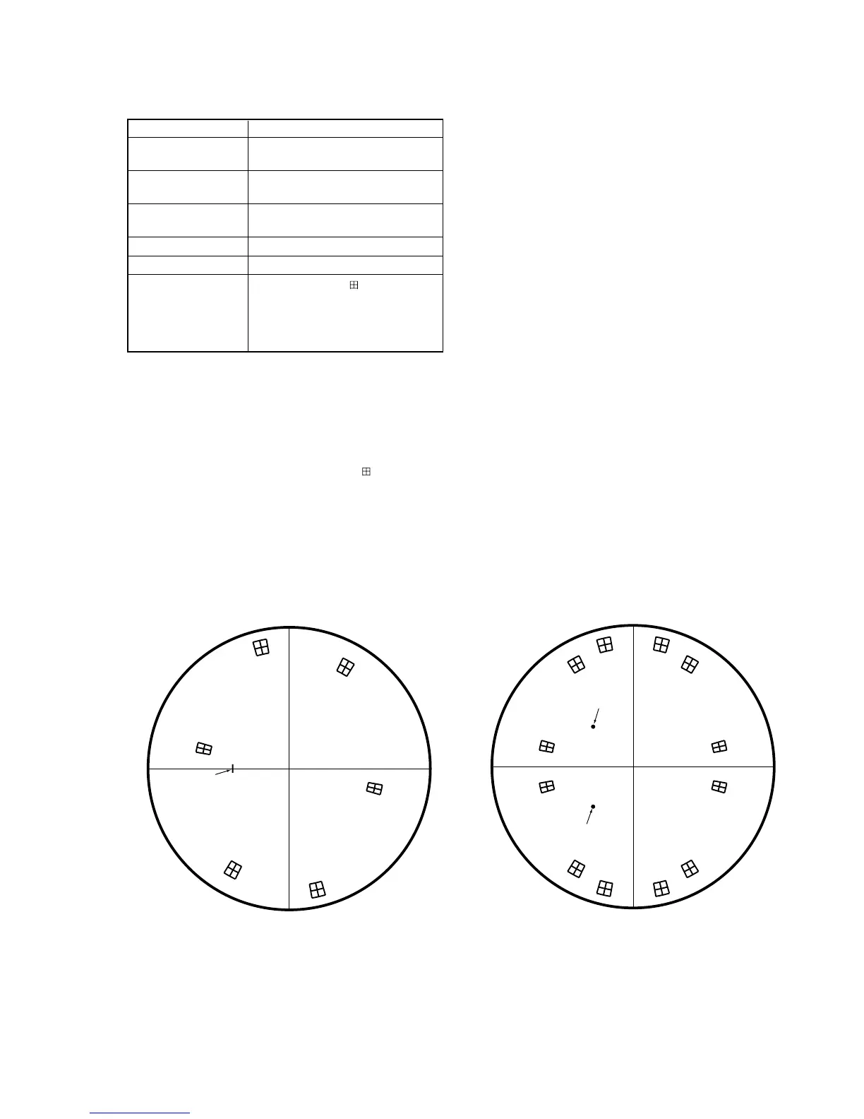
Specified Value From the center of
mark on the
vectorscope, each luminance point
must satisfy the following:
Level: ± 5%
Phase: ± 3º
Note: Set “S VIDEO” mode with INPUT SELECT switch
Adjusting method:
1) Select page: 0, address: 01, and set data: 01.
2) Adjust the burst luminance point to the specified position us-
ing the PHASE and GAIN knobs of vectorscope.
3) Change the data on page: E, address: 93 and adjust so that a
blue luminance point positions at the mark on the
vectorscope. At this time, make sure that each luminance point
satisfies the specified value.
4) Press the PAUSE button of the adjustment remote commander.
5) Select page: 0, address: 01, and set data: 00.
For PAL modelFor NTSC model
Fig. 5-3-34


 To Next Page