9-25
DVW-250/250P
9-7. Video Adjustment-2
9-7. Video System Adjustment-2
Preparation
• Put the unit into EE mode.
MODE switch/connector panel → PB/EE
Put the unit into STOP mode.
• CONFI switch/connector panel → OFF
• On the setup menu, set PAGE and ITEM as follows. (for
NTSC only)
PAGE : <VIDEO 1> <SET UP LEVEL>
ITEM : MASTER LEVEL → 7.5%
ITEM : INPUT LEVEL → MASTER
ITEM : V BLK REMOTE CNT → OFF
ITEM : OUTPUT LEVEL → MASTER
• On the setup menu, set PAGE and ITEM as follows.
PAGE : <VIDEO 2>
ITEM : VIDEO LEVEL → 0.0%
PAGE : <VIDEO 2>
ITEM : SDI OUT → ON
9-7-1. Pedestal Level Adjustment
Preparation
• Put the unit into EE mode.
• CAMERA/VIDEO/SDI input select switch/connector
panel → VIDEO
• VIDEO LEVEL knob/connector panel → Mechanical
center (Click position)
• Inputs the composite video signal to the VIDEO IN
connector on the connector panel.
Signal generator : 75 % Color bars
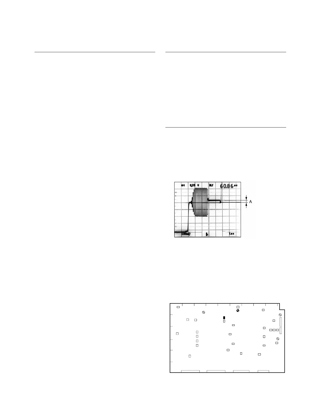
Adjustment procedure
1. Equipment : Oscilloscope
Test point : VIDEO OUT1 connector /
connector panel
Adjustment point : 1RV202 (F-1)/VPR-12
Specification : 0 ±3 mV
VPR-12 Board A side
1
AB
CD EF GHJ
K
2
3
4
5
6
TP203
RV202