9-27
DVW-250/250P
9-7-3. CAMERA RETURN VIDEO Level
Adjustment
Preparation
• Put the unit into EE mode.
MODE switch/connector panel → SAVE
Push the REC button on the front panel.
• CAMERA/VIDEO/SDI input select switch/connector
panel → VIDEO
• Inputs the composite video signal to the VIDEO IN
connector on the connector panel.
Signal generator : 75 % Color bars
Adjustment procedure
1. Equipment : Waveform monitor
Test point : VIDEO OUT 1 connector on the
connector panel
Adjustment point : 1RV200 (K-1) /VPR-12
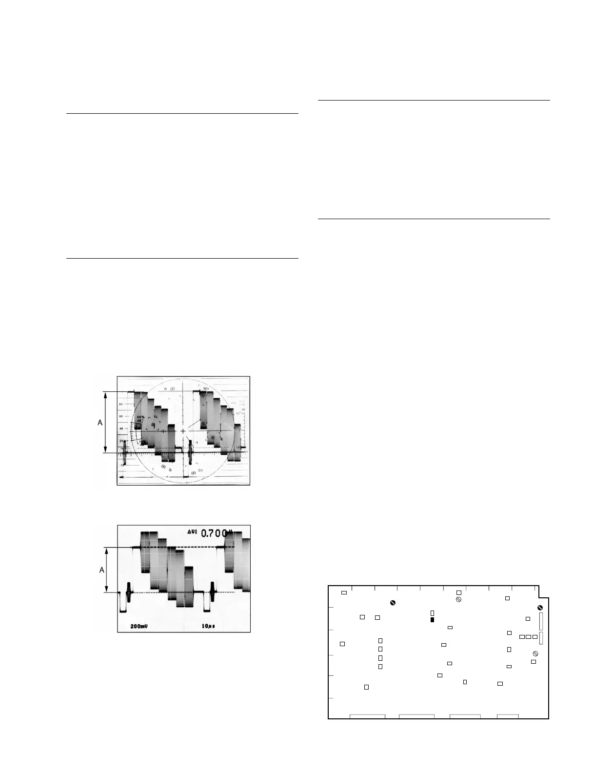
Specification : A = 714 ±7 mV p-p (for NTSC)
A = 700 ±7 mV p-p (for PAL)
[For NTSC]
[For PAL]
2. Setting after adjustment
Reset switches to the former positions.
(MODE switch/connector panel → PB/EE)
9-7-4. INPUT SYNC Level Adjustment
Preparation
• Put the unit into EE mode.
• CAMERA/VIDEO/SDI input select switch/connector
panel → VIDEO
• Inputs the composite video signal to the VIDEO IN
connector on the connector panel.
Signal generator : 75 % Color bars
Adjustment procedure
Equipment : Oscilloscope
(20 MHz BW Limit : ON)
Test point : TP208 (E-2) /VPR-12
Adjustment point : 1RV201 (C-1) /VPR-12
Specification : A = 3.00 ±0.05 V dc
9-7. Video Adjustment-2
VPR-12 Board A side
1
AB
CD EF GHJ
K
2
3
4
5
6
TP208
RV200
RV201


 To Next Page