13
Example of System Configuration
Chapter 1 Overview
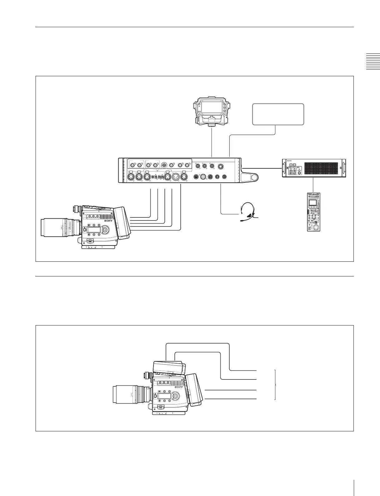
1-2-3 System Using the HDFA-200
A multi-camera system can be established by connecting
the camera to an optional HDFA-200 Optical Fiber
Adaptor Unit.
For details, refer to the Operation Manual of the HDFA-
200.
1-2-4 System Using Two Interface Boxes
By attaching two interface boxes to the camera, Quad Link
output of HD SDI signals, such as 50P 4:4:4, to an external
device is enabled.
For purchasing of an additional interface box, consult a
Sony sales personnel.
CAM-MAIN
(
L
)
REF OUT SDI IN
CAM-SUB
(
R
)
SDI1 OUT SDI2 OUT TEST OUT
AUX CRANE TRACKER RET CTRL DC OUT
0.5A max
DC OUT
4A max
CAM-SUB
(
R
)
DC OUT
CAM-MAIN
(
L
)
DC OUT
DC INAUDIO IN 2AUDIO IN 1
PROMPTER1/
GENLOCK IN
CAM-MAIN
(
L
)
REMOTE
CAM-SUB
(
R
)
REMOTE
REMOTE VF
REF OUT SDI IN
MIC MIC
LINE
OFF
+48V
AES/EBU
LINE
OFF
+48V
60
5.6
8
11
16
CL
2.8
2
1.6
T
ff
4
30
20
15
12
10
8
7
6
5.6
5
4.6
SDI IN
(CAM-SUB(R))
DC OUT
REF OUT
SDI IN
REMOTE
CAM-MAIN
(
L
)
INTERCOM
VF
SDI2 OUT
HDVF-C950W/C730W/C550W/EL75 Viewfinder
Optical fiber
cable
Intercom headset
RCP-1000-series
Remote Control Unit
Video monitor
HDCU1000+HKCU-HB10
Camera Control Unit
Interface box (supplied
with the camera)
HDFA-200
HD-SDI B
HD-SDI A
Link B
Link A
Link D
Link C
HD-SDI B
HD-SDI A
External device
Interface box
(supplied with the camera
or an additional one)
Interface box
(supplied with the camera
or an additional one)