HCD-BX77DBi
14
TUNER SECTION
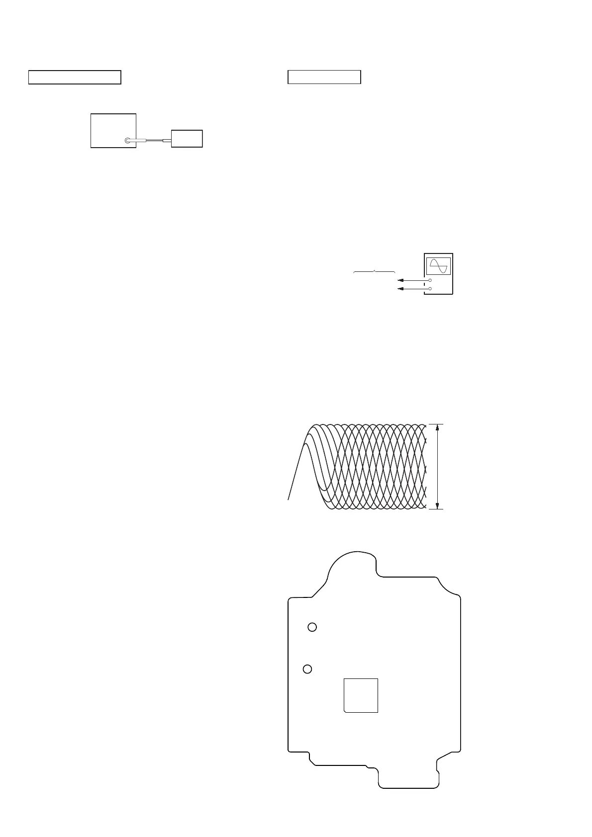
FM TUNE LEVEL CHECK
signal
generator
set
Procedure:
1. Turn on the set.
2. Input the following signal from signal generator to FM antenna input
directly.
Carrier frequency : A = 87.5 MHz, B = 98 MHz, C = 108 MHz
Deviation : 75 kHz
Modulation : 1 kHz
ANT input : 35 dBu (EMF)
Note: Use 75 ohm coaxial cable to connect signal generator and the set.
You cannot use video cable for checking.
Use signal generator whose output impedance is 75 ohm.
3. Set to FM tuner function and tune A, B and C signals.
4. Confi rm “TUNED” is lit on the display for A, B and C signals.
When the selected station signal is received in good condition, “TUNED”
is displayed.
SECTION 4
ELECTRICAL CHECKS
CD SECTION
Note:
1. CD Block is basically constructed to operate without adjust-
ment.
2. Use YEDS-18 disc (Part No. 3-702-101-01) unless otherwise
indicated.
3. Use an oscilloscope with more than 10 MΩ impedance.
4. Clean the object lens by an applicator with neutral detergent
when the signal level is low than specifi ed value with the fol-
lowing checks.
5. Check the focus bias check when optical pick-up block is re-
placed.
FOCUS BIAS CHECK
+
–
CD board
TP121 (RFI)
TP124 (VC)
oscilloscope
(DC range)
Procedure:
1. Connect oscilloscope to TP121 (RFI) and TP124 (VC) on the
CD board.
2. Press the [
?/1
] button to turn the power on.
3. Set disc (YEDS-18) on the disc tray and press the [CD
u
]
button to playback.
4. Confi rm that oscilloscope waveform is as shown in the fi gure
below. (eye pattern)
A good eye pattern means that the diamond shape (◊) in the
center of the waveform can be clearly distinguished.
VOLT/DIV: 200 m
TIME/DIV: 500 ns
level:
1.2 ± 0.3 Vp-p
Checking Location:
\
TP124
(VC)
– CD Board (Conductor Side) –
TP121
(RFI)
IC101