27
HCD-HP8V
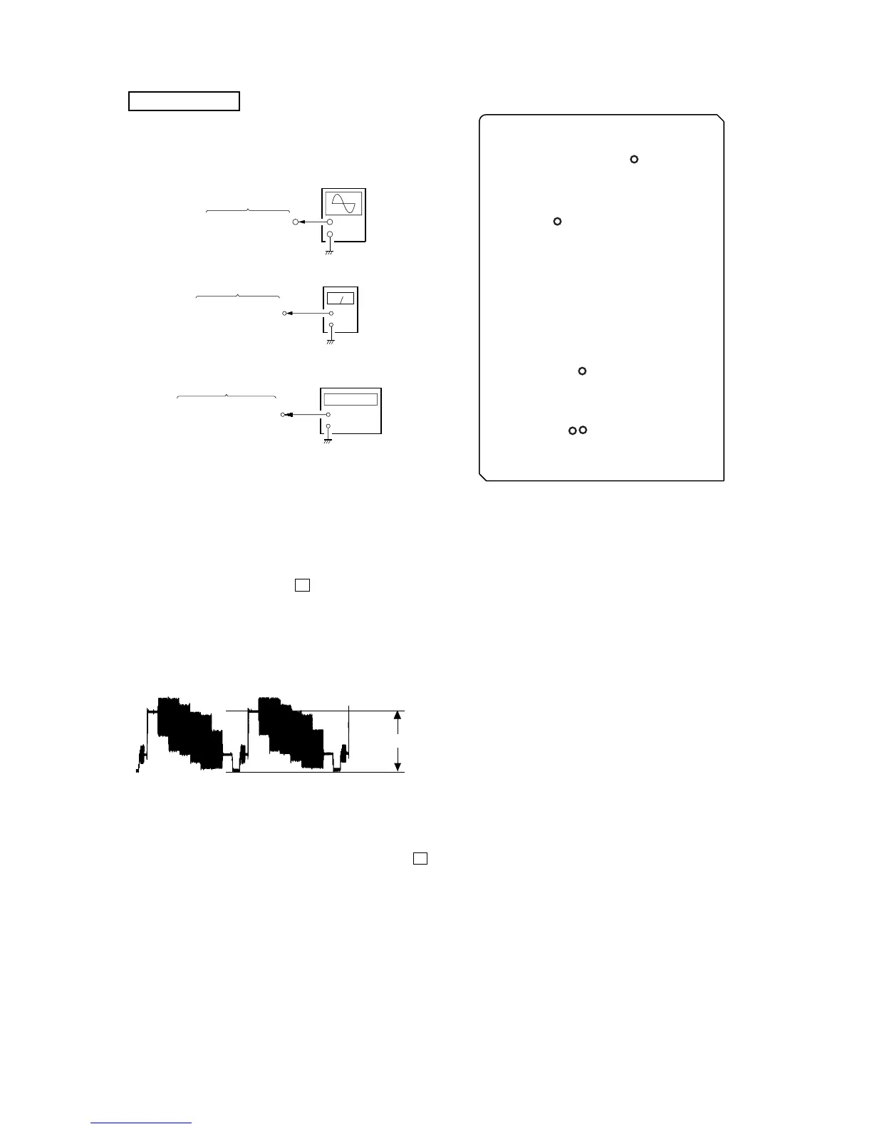
– VMP BOARD (Component Side) –
TP308
(V-OUT)
TP70
(54 MHz)
TP182
(4.2336 MHz)
TP415
(L-OUT)
TP413
(R-OUT)
VIDEO SECTION
Video Level Check
(Audio Level/Video Clock/Audio Servo Clock Check)
Procedure :
1. Connect an oscilloscope to TP308 (V-OUT) on the VMP board.
2. Connect a level meter to TP415 (L-OUT) and TP413 (R-OUT)
on the VMP board.
3. Connect a frequency counter to TP70 (54 MHz) and TP182
(4.2336 MHz) on the VMP board.
4. Turn the power ON.
5. Set a test disc (HLV-402 (Part No. 8-909-870-00))
6. Press three buttons
[DISPLAY], x and [DISC5] simultaneously.
7. Press the [DIMMER] button. The message “MPEG AV TEST”
is displayed on the fluorescent indicator. Color bar signal outputs
and sine-wave (1 kHz 0dB) appears.
8. Confirm that the signal at TP308 (V-PUT) on the VMP board is
0.714 ± 0.05 Vp-p.
Note: TP308 (V-OUT) on the VMP board must be teminated by 75 Ω.
9. Confirm that the value of level meter is 2.5 ± 2.0 dBs.
10. Confirm that the value of frequency counter is 54 MHz ± 400
Hz.
11. Confirm that the value of frequency counter is 4,2336 MHz.
12. To exit from this mode, Press three buttons [DISPLAY], x and
[DISC1] simultaneously.
+
–
level mete
 Loading...