49
HCD-MG110/MG310AV
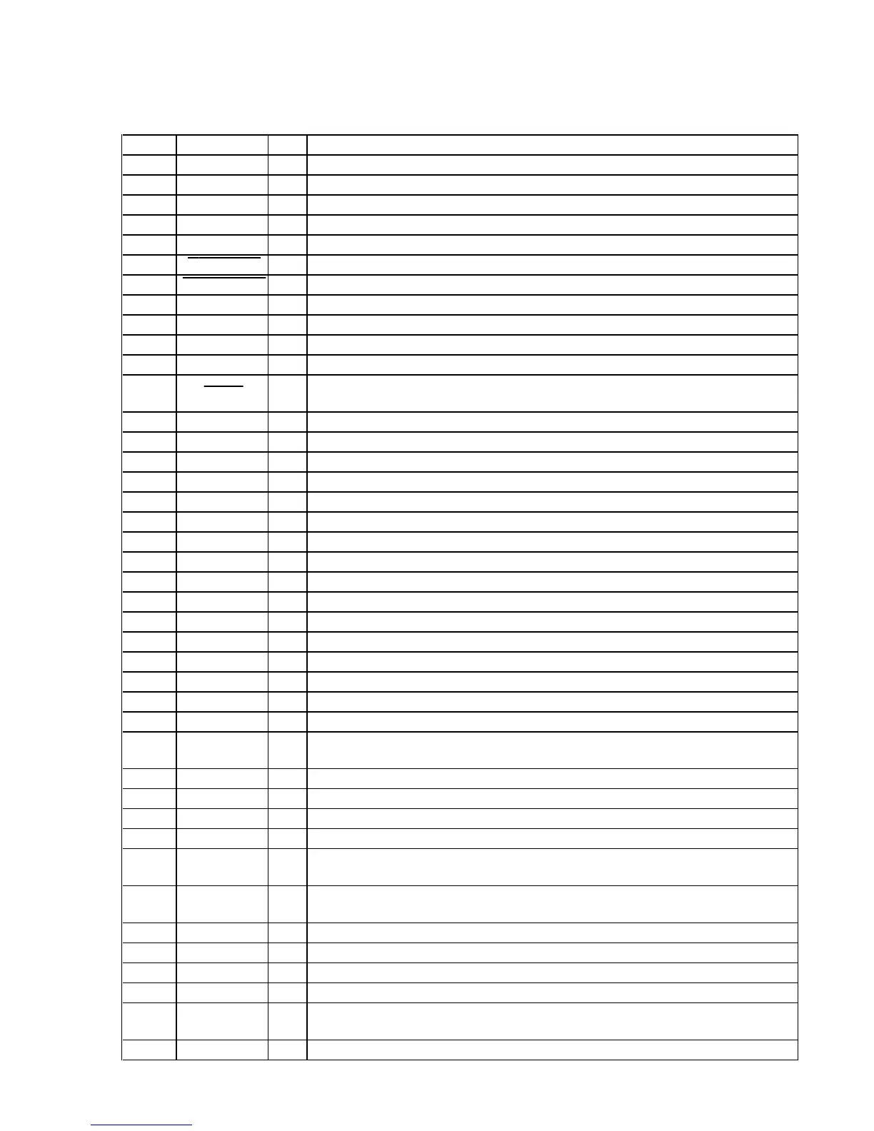
• MAIN BOARD IC801 M30622MGA-A42FP (SYSTEM CONTROLLER)
Pin No. Pin Name I/O Description
1NC—
Not used (open)
2 LOAD POS O
Loading motor drive signal (load-out direction) output the motor driver (IC881)
3 LOAD NEG O
Loading motor drive signal (load-in direction) output the motor driver (IC881)
4RMCI
Remote control signal input from the remote control receiver (IC702)
5 TABLE POS O
Table motor drive signal (counterclockwise) output to the motor driver (IC881)
6 LOAD IN SW I
Load in/out detect switch (S842) input “L”: load in
7 LOAD OUT SW I
Load in/out detect switch (S842) input “L”: load out
8 ——
Not used (fixed at “L”)
9 CNVSS —
Not used
10 SUBXIN I
Sub system clock input terminal (32.768 kHz)
11 SUBXOUT O
Sub system clock output terminal (32.768 kHz)
12 RESET I
System reset signal input from the reset signal generator (IC802) “L”: reset
For several hundreds msec. after the power supply rises, “L” is input, then it changes to “H”
13 XOUT O
Main system clock output terminal (16 MHz)
14 VSS —
Ground terminal
15 XIN I
Main system clock input terminal (16 MHz)
16 VCC —
Power supply terminal (+5V)
17 NC —
Not used (fixed at “H”)
18 T-SENS2 I
Table position sensor (IC13) input terminal
19
SCOR
I
Subcode sync (S0+S1) detection signal input from the CXD3017Q (IC101)
20
KB-SCL
O
Serial data transfer clock signal output to the KEYBOARD (J801)
21 C-MUTE O
Muting on/off control signal output terminal “H”: muting (center speaker) (MG310AV only)
22 PWM1 O
Focus servo drive PWM signal output to the CXA2581N (IC103)
23 R-MUTE O
Muting on/off control signal output terminal “H”: muting (rear speakers) (MG310AV only)
24 PWM2 O
PWM signal output to the CXA2581N (IC103)
25 PL-RQ O
Serial data latch pulse output to the M62464FP (IC401) (MG310AV only)
26 PWM3 O
RFDC PWM signal output to the CXA2581N (IC103)
27 PL-DATA O
Serial data output to the M62464FP (IC401) (MG310AV only)
28 PL-CLK O
Serial data transfer clock signal output to the M62464FP (IC401) (MG310AV only)
29 IIC CLK I/O
Communication data reading clock signal input or transfer clock signal output with the display
controller (IC701)
30 IIC DATA I/O
Communication data bus with the display controller (IC701)
31 NC —
Not used
32 C-SQSO I
Subcode Q data input from the CXD3017Q (IC101)
33
C-SQCK
O
Subcode Q data reading clock signal output to the CXD3017Q (IC101)
34 FRONT O
Selection signal output of the rear speaker output signal to the BU4066BC (IC307)
“H”: Same the front channel (MG310AV only)
35 REAR O
Selection signal output of the rear speaker output signal to the BU4066BC (IC307)
“H”: Rear channel (MG310AV only)
36 KB-SDA
I Keyboard data input from the KEYBOARD (J801)
37 KB-CTRL
O Keyboard control signal output to the KEYBOARD (J801)
38 S/W MUTE
O Muting on/off control signal output terminal “H”: muting (super woofer) (MG310AV only)
39 NC —
Not used (open)
40 R-RELAY O
Relay drive signal output for the surround speaker (rear and center) protection “H”: on
(MG310AV only)
41 NC —
Not used (fixed at “L”)
• MAIN BOARD IC801
M30622MGA-A68FP (SYSTEM CONTROLLER)
Ver 1.1