52
HCD-MG110/MG310AV
• DISPLAY BOARD IC701 MB90M407APF-G-104-BND (DISPLAY CONTROLLER)
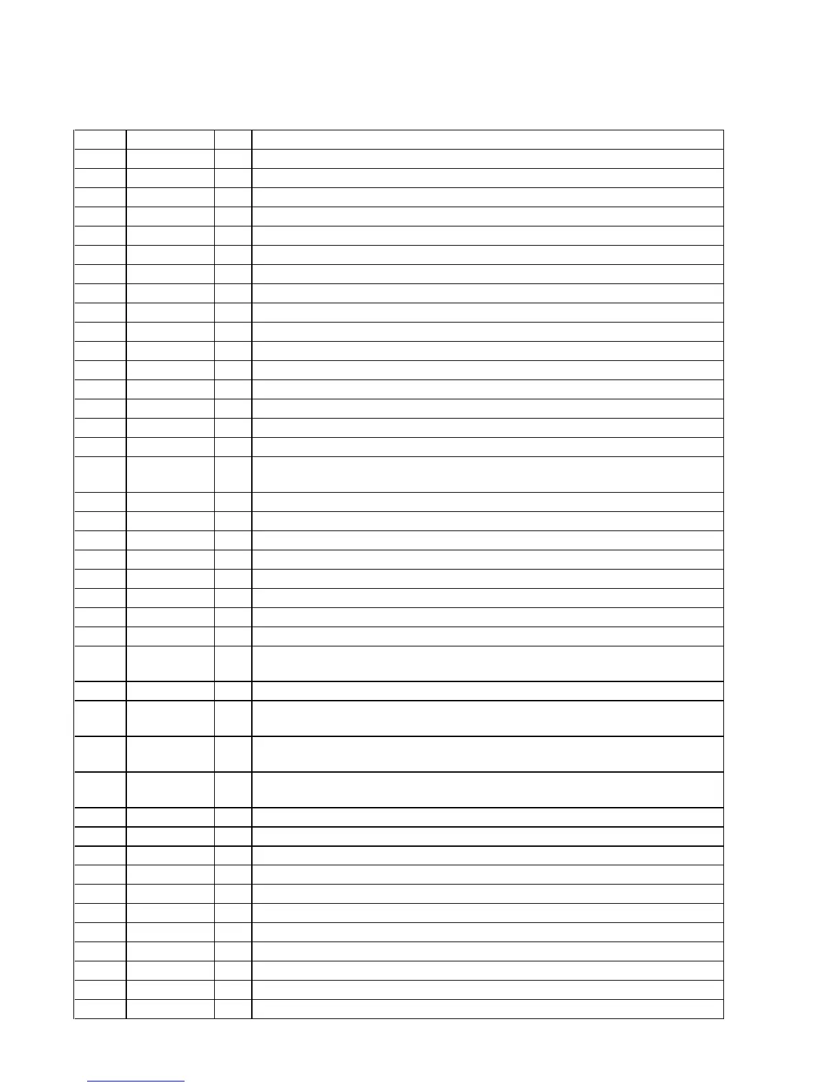
Pin No. Pin Name I/O Description
1 to 10 G4 to G13 O
Grid drive signal output to the fluorescent indicator tube (FL701)
11 VSS-IO —
Ground terminal
12 to 22 S34 to S24 O
Segment drive signal output to the fluorescent indicator tube (FL701)
23 VDD-FIP —
Power supply terminal (+3.3V)
24 to 41 S23 to S6 O
Segment drive signal output to the fluorescent indicator tube (FL701)
42 VSS-IO —
Ground terminal
43 to 47 S5 to S1 O
Segment drive signal output to the fluorescent indicator tube (FL701)
48 VKK —
Power supply terminal (–33V) (for fluorescent indicator tube drive)
49 to 51 MD0 to MD2 —
Not used (fixed at “H”)
52, 53 IC0, IC1 —
Not used (open)
54 SI0 —
Not used (open)
55 SC0 —
Not used (open)
56 SO0 —
Not used (open)
57 SI1 —
Not used (open)
58 SC1 —
Not used (open)
59 DOOR SW I
CD lid open/close detest switch (S791) input terminal “L”: CD lid is close
60 SDA I/O
Communication data reading clock signal input or transfer clock signal output with the system
controller (IC801)
61 SCL I/O
Communication data bus with the system controller (IC801)
62 AVCC —
Power supply terminal (+3.3V) (for A/D converter)
63 AVSS —
Ground terminal (for A/D conversion)
64, 65 JOG A, JOG B I
Jog dial pulse input from the rotary encoder (RV702 DISC ACCESS)
66, 67 VOL A, VOL B I
Jog dial pulse input from the rotary encoder (RV701 VOLUME)
68 to 70 PA4 to PA6 —
Not used (open)
71 L+R I
Spectrum analyzer drive signal input from the spectrum analyzer band-pass filter (IC703)
72 to 75 BPF4 to BPF1 I
Spectrum analyzer drive signal input from the spectrum analyzer band-pass filter (IC704)
76 KEY3 I
Key input terminal (A/D input) (S771 to 777) PLAY MODE, REPEAT STEREO/MONO, CD
SYNCRO, z REC, CLEAR, DIRECTION, MENU keys input
77 XRST I
Reset signal input from the system controller (IC801)
78 KEY2 I
Key input terminal (A/D input) (S760 to 767) TIMER SELECT, TIMER SET, m, M,
TUNER/BAND, CD, TAPE A/B, 5.1CH/VIDEO (MD) keys input
79 KEY1 I
Key input terminal (A/D input) (S750 to 757) SURROUND MODE, PRESET EQ, ENTER, –
., > +, X PAUSE, x, n N keys input
80 KEY0 I
Key input terminal (A/D input) (S741 to 745) LINK, REAR, FRONT, PRO LOGIC,
SURROUND keys input
81 CPU VSS
— Ground terminal
82 X0 I
System clock input terminal (4 MHz)
83 X1 O
System clock output terminal (4 MHz)
84 VCC-CPU
— Power supply terminal (+3.3V)
85 COM
— Not used (open)
86 LED0 O
LED drive signal output terminal (I/1)
87 LED1 O
LED drive signal output terminal (PRESET EQ)
88 LED2 O
LED drive signal output terminal Not used (open)
89 LED3 O
LED drive signal output terminal (SURROUND) (MG310AV only)
90 LED4 O
LED drive signal output terminal (PRO LOGIC) (MG310AV only)
91 LED5 O
LED drive signal output terminal (FRONT) (MG310AV only)



 To Next Page