HCD-SHAKE10/SHAKE30/HCDSHAKEX10/HCDSHAKEX30/HCDSHAKEX70
25
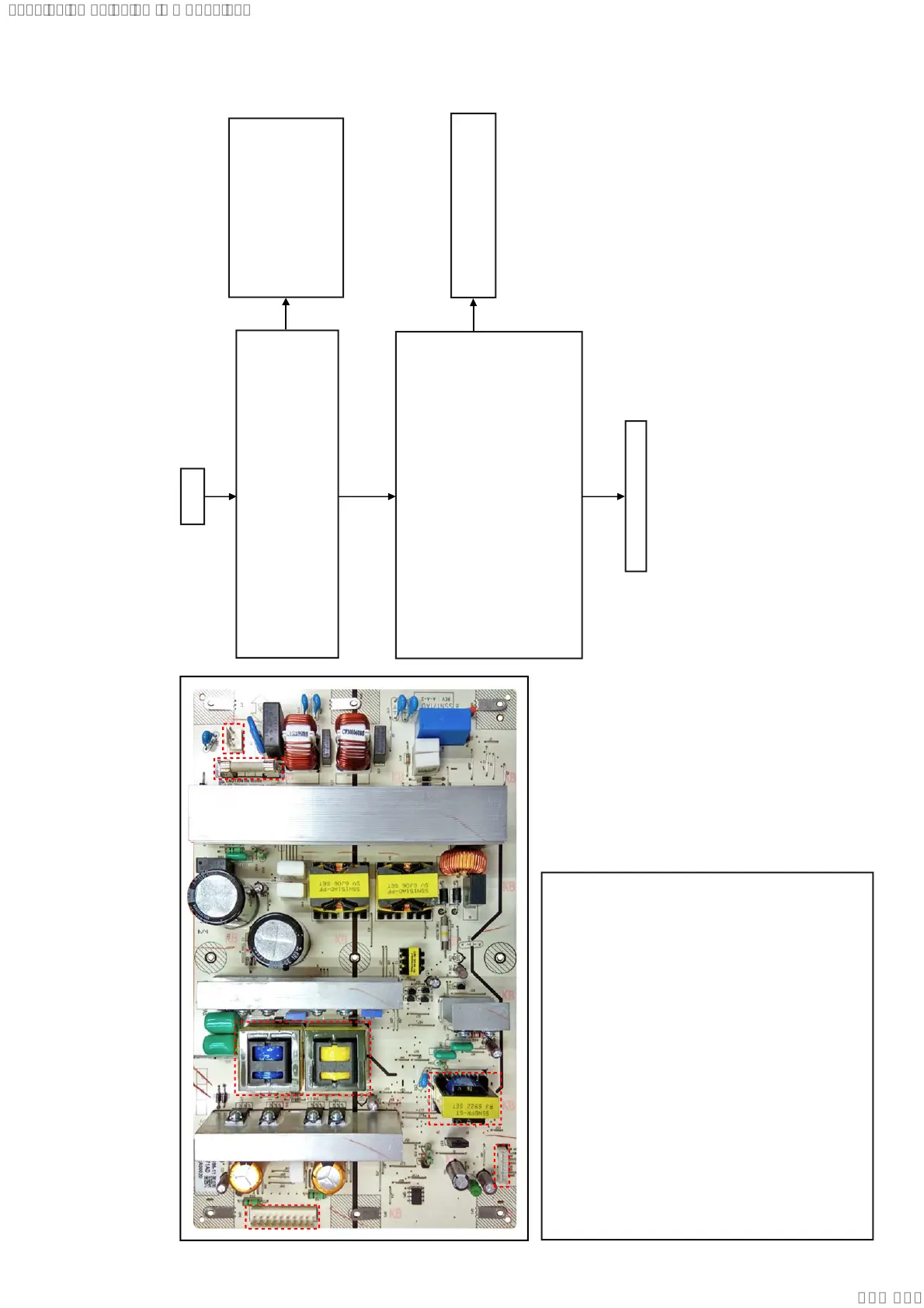
Switching Regulator (SSN-171AD) Diagnosis Flow (HCDSHAKEX70)
(1) AC input
(2) Fuse
(3) Sub Power transformer
(4) CN 4 Connector
pin1: Audio (13.5V)
pin2: Audio (GND)
pin3-4: LED (13.5V)
pin5-6: LED (GND)
pin7: AC-Det
pin8: PCON
pin9: LOW AC
(5) MAIN Power transformer
(6) CN 2 Connector
pin1: SPV (DC-45.5V)
pin2-4: -PVDD (DC-62.5V)
pin5: -VL (DC-24V)
pin6: GND
pin7: +VL (DC+24V)
pin8-10: +PVDD (DC+62.5V)
The Output from Switching regulator is checked.
Is following power voltage up to standard?
Standby Demo mode Power On
CN4 pin1
CN2 pin2-4
AC IN
Yes
No
Yes
END
No
Check whether the state of the
Cable and Outlet are normal.
If there are no problems, check
circumference circuit for Main
on/Sub on Output of the
Motherboard mount side.
Replaces Switching regulator if it
is not up to standard.
The Power Control signal to Switching regulator is checked.
Is following power voltage OK?
Main on/Sub on Standby Demo mode Power On
CN 4 :pin8 Low (0V) Low (0V) Hi (3.3V)
13.5V±0.5V
13.5V±0.5V 13.5V±0.5V
0V 0V
pin5 0V 0V
pin7 0V 0V
pin8-10 0V 0V
pin1 0V 0V
-62.5V±5%
-24V±5%
+24V±5%
+62.5V±5%
-45.5V±10%
(6)
(4)
(3)
(5)
(2)
(1)
SYSSET
2019/10/2523:34:43(GMT+09:00)