27
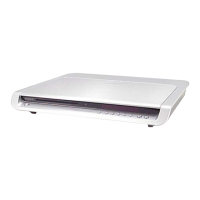
HCD-SR4W
[TEST DISC LIST]
Use the following test disc on test mode.
TDV-520CSO (DVD-SL) : PART No. J-2501-236-A
LUV-P01 (CD) : PART No. 4-999-032-01
TDV-540C (DVD-DL) : PART No. J-2501-235-A
Note: Do not use exiting test disc for DVD.
AUTO SERVO ADJUSTMENT
After parts related to the servo circuit (RF amplifier (IC001), DSP
(IC401), motor driver (IC501), EEPROM (IC302) so on) and optical
pick-up (DBU-1) are replaced, re-adjusting the servo circuit is
necessary. Select “ALL” at “1. DRIVE AUTO ADJUSTMENT”
(Refer to page 25 in TEST MODE) and adjust DVD-SL (single
layer), CD and DVD-DL (dual layer).
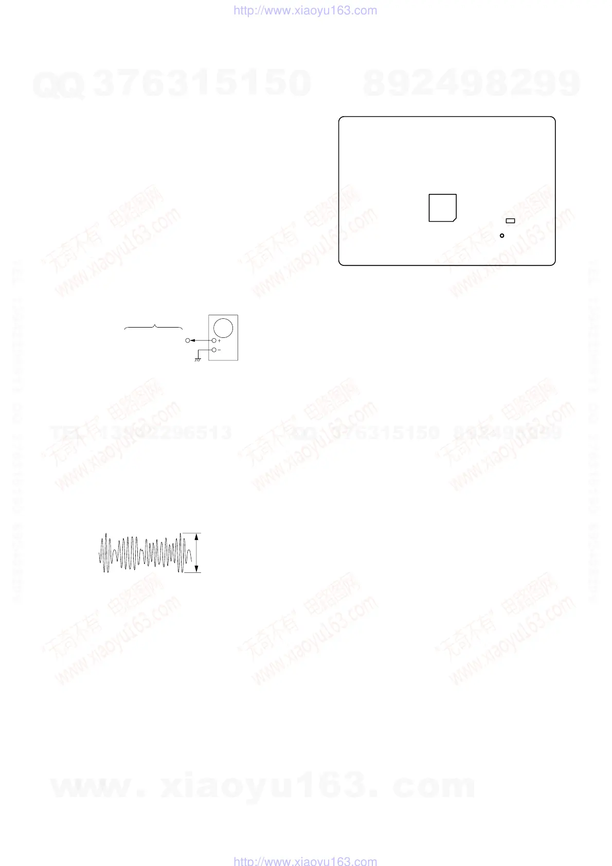
DIAT SIGNAL RF LEVEL ADJUSTMENT
This adjustment is performed in order to adjust the transmission
distance of RF signal for DIAT communication.
Connection:
Procedure:
1. Connect the oscilloscope to TP815 (RF AMP OUT) and GND
on the DIAT TRANSMIT board.
2. Connect DIR-T1 to DIR-T1 jack (J301).
3. Adjust RV801 on the DIAT TRANSMIT board so that the
center of waveform becomes 1.0 Vp-p.
4. Confirm trigger is locked.
5. Adjust RV801 on the DIAT TRANSMIT board so that the
center of waveform becomes 2.2 to 2.4 Vp-p.
RF Signal Reference Waveform
SECTION 5
ELECTRICAL ADJUSTMENT
VOLT/DIV : 500 mV
TIME/DIV : 500 ns
level : 2.2 to 2.4 Vp-
– DIAT TRANSMIT Board (SIDE A) –
TP815
(RF AMP OUT)
IC804
IC805
TP815
(RF AMP OUT)
DIAT TRANSMIT
board
oscilloscope
Adjustment Location:
w
w
w
.
x
i
a
o
y
u
1
6
3
.
c
o
m
Q
Q
3
7
6
3
1
5
1
5
0
9
9
2
8
9
4
2
9
8
T
E
L
1
3
9
4
2
2
9
6
5
1
3
9
9
2
8
9
4
2
9
8
0
5
1
5
1
3
6
7
3
Q
Q
TEL 13942296513 QQ 376315150 892498299
TEL 13942296513 QQ 376315150 892498299
http://www.xiaoyu163.com
http://www.xiaoyu163.com