2
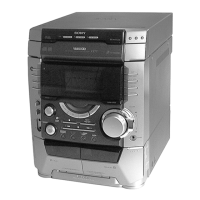
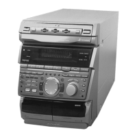
General
Power requirements
Thailand models: 220 V AC, 50/60 Hz
Other models: 120 V, 220 V or 230 - 240
V AC, 50/60 Hz
Adjustable with voltage
selector
Power consumption
250 watts
Dimensions (w/h/d)
Approx. 280 x 360 x 425
mm (11
x 14
3
/
16
x 16
11
/
16
in.)
Mass:
Approx. 9.5 kg
(21 lb.)
Supplied accessories: AM loop antenna (1)
Remote commander (1)
Batteries (2)
Video cable (1)
FM lead antenna (1)
Front speaker pads (8)
Design and specifications are subject to change
without notice.
TABLE OF CONTENTS
1. SERVICE NOTE ······························································· 4
2. GENERAL ·········································································· 5
3. DISASSEMBLY ································································ 7
4. TEST MODE ···································································· 12
5. MECHANICAL ADJUSTMENTS ····························· 17
6. ELECTRICAL ADJUSTMENTS ······························· 17
7. DIAGRAMS
7-1. Circuit Board Location ····················································· 23
7-2. Block Diagrams – TUNER/CD Section – ························ 25
7-3. Printed Wiring Board – BD Section – ······························ 28
7-4. Schematic Diagram – BD Section – ································· 29
7-5. Printed Wiring Board – Video Section – ·························· 30
7-6. Schematic Diagram – Video (1/3) Section – ···················· 31
7-7. Schematic Diagram – Video (2/3) Section – ···················· 32
7-8. Schematic Diagram – Video (3/3) Section – ···················· 33
7-9. Printed Wiring Board – Main Section – ··························· 34
7-10. Schematic Diagram – Main (1/3) Section – ····················· 35
7-11. Schematic Diagram – Main (2/3) Section – ····················· 36
7-12. Schematic Diagram – Main (3/3) Section – ····················· 37
7-13. Printed Wiring Board – Power AMP Section – ················ 38
7-14. Schematic Diagram – Power AMP Section – ··················· 39
7-15. Printed Wiring Board – Panel Section – ··························· 40
7-16. Schematic Diagram – Panel Section – ····························· 41
7-17. Printed Wiring Board – Leaf SW Section – ····················· 42
7-18. Schematic Diagram – Leaf SW Section – ························ 43
7-19. Printed Wiring Board – Driver Section – ························· 44
7-20. Schematic Diagram – Driver Section – ···························· 45
7-21. Printed Wiring Board – Trans Section – ··························· 46
7-22. Schematic Diagram – Trans Section – ····························· 47
7-23. IC Pin Function ································································ 48
7-24. IC Block Diagrams ··························································· 57
8. EXPLODED VIEWS
8-1. Main Section····································································· 61
8-2. Panel Section ···································································· 62
8-3. Main Board Section ·························································· 63
8-4. Tape Mechanism Deck Section-1 ····································· 64
8-5. Tape Mechanism Deck Section-2 ····································· 65
8-6. CD Mechanism Deck Section (CDM58-K2BD37A) ······· 66
8-7. Base Unit Section (BU-K2BD37A) ································· 67
9. ELECTRICAL PARTS LIST ······································· 68
Ver 1.1 2001.08