2-2 (E)
HDCU3300/MM (J, E)
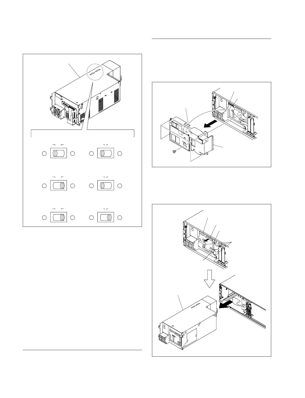
Replacement Procedure
1. Remove the front panel.
2. Remove the four screws and remove the flexible card
wire from the CN9003 on the CN-3275 board.
3. Remove the PS panel assembly.
4. Remove the harnesses from the CN9002, CN9006 and
CN9007 on the CN-3275 board.
5. Remove the power block assembly (A10) from
HDCU3300 in the direction of the arrow.
Switching regulator
220-240V110-120V115V100V
CAMERA TRANS
220-240V110-120V115V100V
CAMERA TRANS
. UC : 110V-120V
. J : 100V
220-240V110-120V115V100V
CAMERA TRANS
. CE, CN : 220V-240V
6. Set the two voltage selectors on the new switching
regulator to the settings shown in the diagram.
7. Confirm if the CAMERA fuse of the replacement
power supply unit adapts to the working power supply
voltage. If not, replace it with the one adapting to the
working power supply voltage.
(Refer to Section 2-1-2.)
n
If the rating of the fuse doesn’t adapt to the working
power supply voltage, the safety can not be ensured.
So, the CAMERA fuse needs to be replaced with the
one adapting to the working power supply voltage.
8. Install the power supply unit by reversing the steps of
removal.
Power Block Assembly (A10) (A-1768-444-A)
Replacement Part
Part: Power block assembly (A10)
Part No. : ! A-1768-444-A
Flexible card wire
(26 strand)
PS panel assembly
Screws
(B4 x 10)
CN9003
CN-3275 board
CN-3275 board
Harnesses
Power block assembly (A10)
CN9002
CN9006
CN9007