3-4 (E)
HDCU3300/MM (J,E)
3-2. Audio System Adjustment
3-2-1. Microphone Level Adjustment
Measures : Oscilloscope, Audio oscillator
Note
This adjustment is described on the premise that the output
impedance of the audio oscillator is 600 Z.
Preparation
. To be extended : AVP-6 board (front side)
. To be extended : AU-298 board (camera side)
. Set CHU MIC GAIN CH1 on page “C05” of the config-
uration menu to 20 dB.
. Set CHU MIC GAIN CH2 on page “C05” of the config-
uration menu to 20 dB.
. S500 (F-3)/AVP-6 board → 0 dBu
. S501 (F-3)/AVP-6 board → 0 dBu
. Set the rear microphone on the camera side to MIC for
both audio 1 and 2.
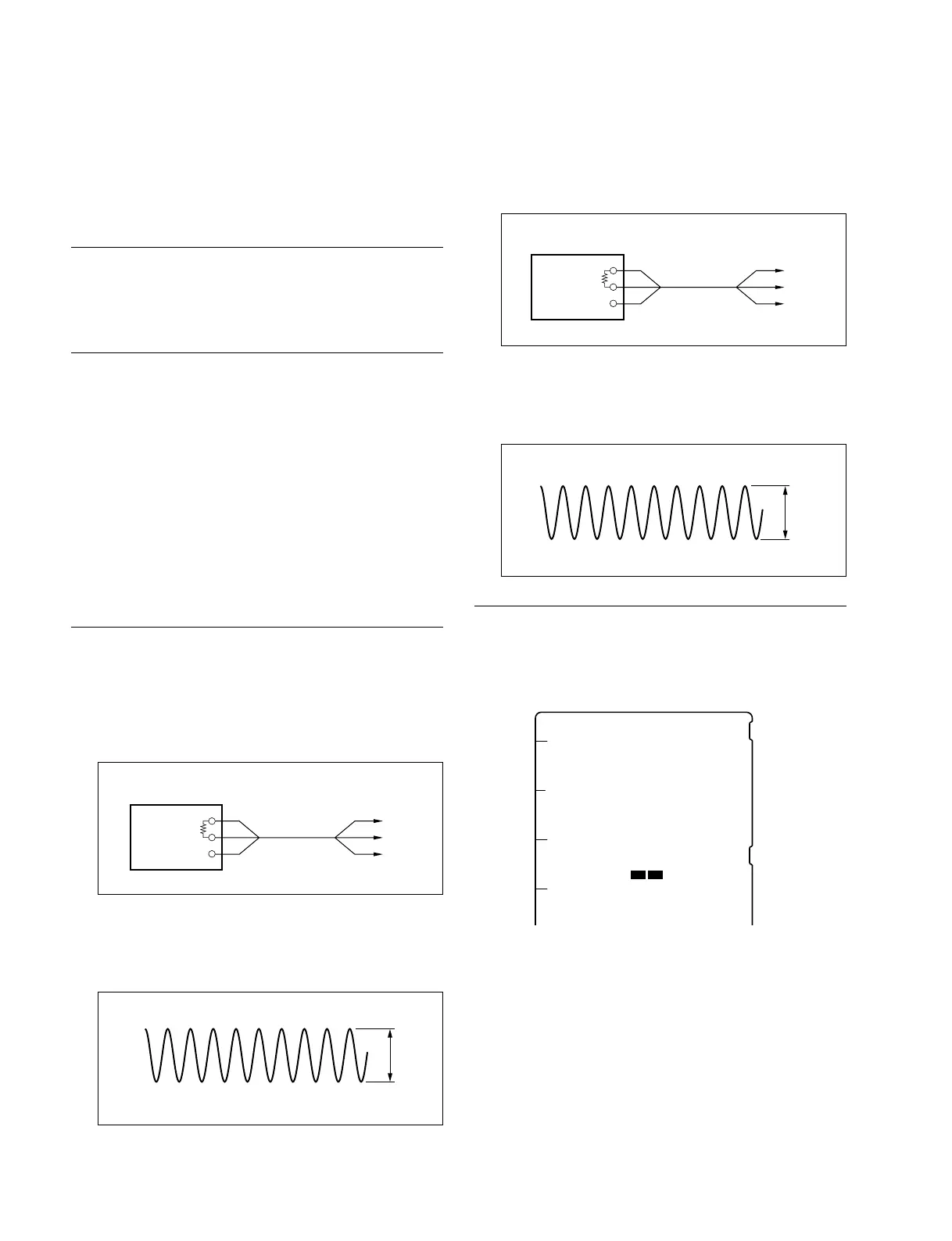
Adjustment Procedure
1. MIC1 level adjustment
Input a sine wave of 1 kHz, 220 mV p-p (_20 dBu)
from the audio oscillator to 185-pin (X), 183-pin (Y)
and 181-pin (G) of the extension board (camera side).
2. Measuring point : TP502 (G-3)/AVP-6 board
Adjusting point : 1RV500 (F-3)/AVP-6 board
Specifications : A = 1100 ± 50 mV p-p
3. Remove the cable that is connected in step 1.
4. MIC2 level adjustment
Input a sine wave of 1 kHz, 220 mV p-p (_20 dBu)
from the audio oscillator to 155-pin (X), 153-pin (Y)
and 151-pin (G) of the extension board (camera side).
5. Measuring point : TP503 (G-3)/AVP-6 board
Adjusting point : 1RV501 (F-3)/AVP-6 board
Specifications : B = 1100 ± 50 mV p-p
Setting after Adjustment
S500 (F-3), S501 (F-3)/AVP-6 board → Return to the
original setting.
600 Z
Audio oscillator
GND GND
Y
X
A
600 Z
Audio oscillator
GND GND
Y
X
B
EFGHJ
RV501RV500
S501S500
11
AVP-6 board (A side)