3-5 (E)
HDCU3300/MM (J,E)
3-2-2. RTS Intercom Adjustment
Measures : Oscilloscope, Audio oscillator
Note
. This adjustment is described on the premise that the
output impedance of the audio oscillator is 600 Z.
. When the intercom system is the RTS system, perform
this adjustment.
Preparation
. To be extended : AVP-6 board (front side)
. S4/AU-302 board → CARBON
. S602 (C-3)/AVP-6 board → RTS
. S600 (E-4)/AVP-6 board → RTS
. S603 (C-4)/AVP-6 board → RTS
. S601 (E-4)/AVP-6 board → RTS
Adjustment Procedure (PROD CANCEL)
1. S2 (INCOM SELECT)/AU-302 board panel side →
PROD
2. Connect a resistance of 200 Z between a8-pin (CN1
side) and C8-pin of the extension board.
3.
Input a sine wave of 1 kHz, 220 mV p-p (_20 dBu) from
the audio oscillator to 2-pin (X), 1-pin (Y) and 3-pin (G)
of the INCOM connector on the HDCU front panel.
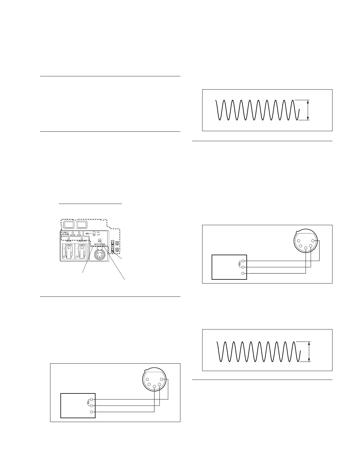
4. PROD CANCEL adjustment
Measuring point : TP600 (B-4)/AVP-6 board
Adjusting point : 1RV600 (PROD 2WIRE CAN-
CEL)/AVP-6 board panel side
Specifications : A = Minimize
Adjustment Procedure (ENG CANCEL)
1. S2 (INCOM SELECT)/AU-302 board panel side →
ENG
2. Connect a resistance of 200 Z between a7-pin (CN4
side) and C7-pin of the extension board.
3. Input a sine wave of 1 kHz, 220 mV p-p (_20 dBu)
from the audio oscillator to 2-pin (X), 1-pin (Y) and 3-
pin (G) of the INCOM connector on the HDCU front
panel.
4. Measuring point : TP601 (B-4)/AVP-6 board
Adjusting point : 1RV601 (ENG 2WIRE CAN-
CEL)/AVP-6 board panel side
Specifications : B = Minimize
Setting after Adjustment
After adjustment is completed, return the switches to the
original setting.
S4
AU-302 board
INCOM control
HDCU3300
600 Z
GND
1
2
3
4
5
Audio oscillator
A
600 Z
GND
1
2
3
4
5
Audio oscillator
B