2-9 (E)
HDCU3300/MM (J, E)
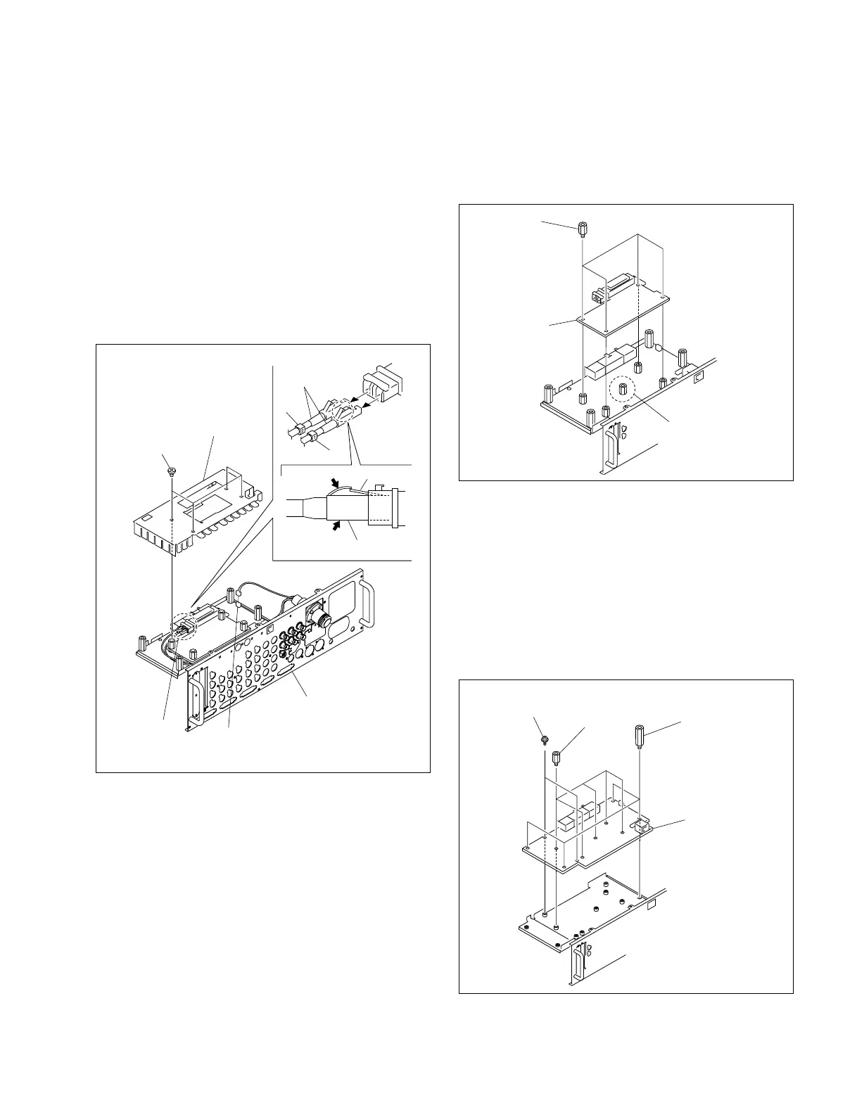
9. Remove the four screws and remove the SDP-15
cover.
10. Disconnect the harness from the connector CN103 on
the SDP-15 board.
11. Disconnect the two optical cables from the connector
CN1001 on the OTR-1 board and remove the rear
panel.
Disconnecting the optical cables
1 Hold the plug of the optical cable and press on the
lock to release it.
2 Pull out the unlocked optical cable.
12. Install the rear panel by reversing the steps of removal.
SDP-15 cover
Screws
(M2.6 x 6)
CN103/
SDP-15 board
CN1001/
OTR-1 board
Rear panel
Optical
cables
Optical cable
Lock
1
2
2-1-5. Replacing the OTR-1 Board
1. Remove the rear panel. (Refer to Section 2-1-4.)
2. Remove the four hexagonal bolts and remove the
OTR-1 board.
3. Install the OTR-1 board by reversing the steps of
removal.
2-1-6. Replacing the SPD-15 Board
1. Remove the rear panel. (Refer to Section 2-1-4.)
2. Remove the OTR-1 board. (Refer to Section 2-1-5.)
3. Remove the two screws, four spacers, five hexagonal
bolts and remove the SDP-15 board.
4. Install the SDP-15 board by reversing the steps of
removal.
OTR-1 board
Hexagonal
bolts
This hexagonal bolt
only supports the
OTR-1 board.
Screws
(PSW3 x 6)
Hexagonal
bolts
SDP-15 board
Spacers



 To Next Page