3-6 (E)
HDCU3300/MM (J,E)
3-3. Video and Reference Signal System
Adjustment
3-3-1. 27 MHz VCO Free-run Adjustment
Measure : Frequency counter, Oscilloscope
Preparation
. To be extended : AT-167S board (front side)
. Remove the cable connected to the REFERENCE IN
connector on the HDCU rear panel.
. S401 (REFERENCE)/AT-167S board panel side
→ SD
. Connect the measure as shown in the following figure.
. After turning on the power, wait for 10 minutes at least
and start adjustment.
Adjustment Procedure
Measuring point : TP704 (F-4)/AT-167S board
Adjusting point : 1RV701 (F-2)/AT-167S board
Specifications : 27,000,000 ± 10 Hz
Setting after Adjustment
After finishing the adjustment, return the switches to the
original configuration. Reconnect the disconnected cables.
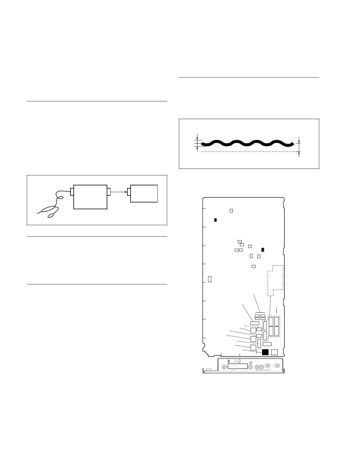
3-3-2. Clock (74 MHz) Duty Adjustment
Measure : Oscilloscope (20 MHz BWLimit: ON)
Adjustment Procedure
Measuring point : TP714 (H-1)/AT-167S board
Adjusting point : 1RV702 (G-1)/AT-167S board
Specifications : C = 1.60 ± 0.04 Vdc
A
B
A=B
C
GND
AB C D E F G HJ
1
2
3
4
5
S403
S404
S405
S410
S409
S408
S407
S406
S419
S418
S402
S401
S420
S416
S411
RV702
RV701
S103
S104
S101
S102
S413
S412
AT
REF IN
UN
LOCK
H PHASE
REFERENCE
HD
RMT
SD
ADV
DELAY
1
1
TP601TP601
TP705
TP703
TP704
TP702
TP709
TP713
TP712
TP711
TP701
TP714
AT-167S board (A side and panel side)
Probe
Oscilloscope
Frequency
counter
CH2
IN
CH2
OUT
IN
 Loading...


