3-7 (E)
HDCU3300/MM (J,E)
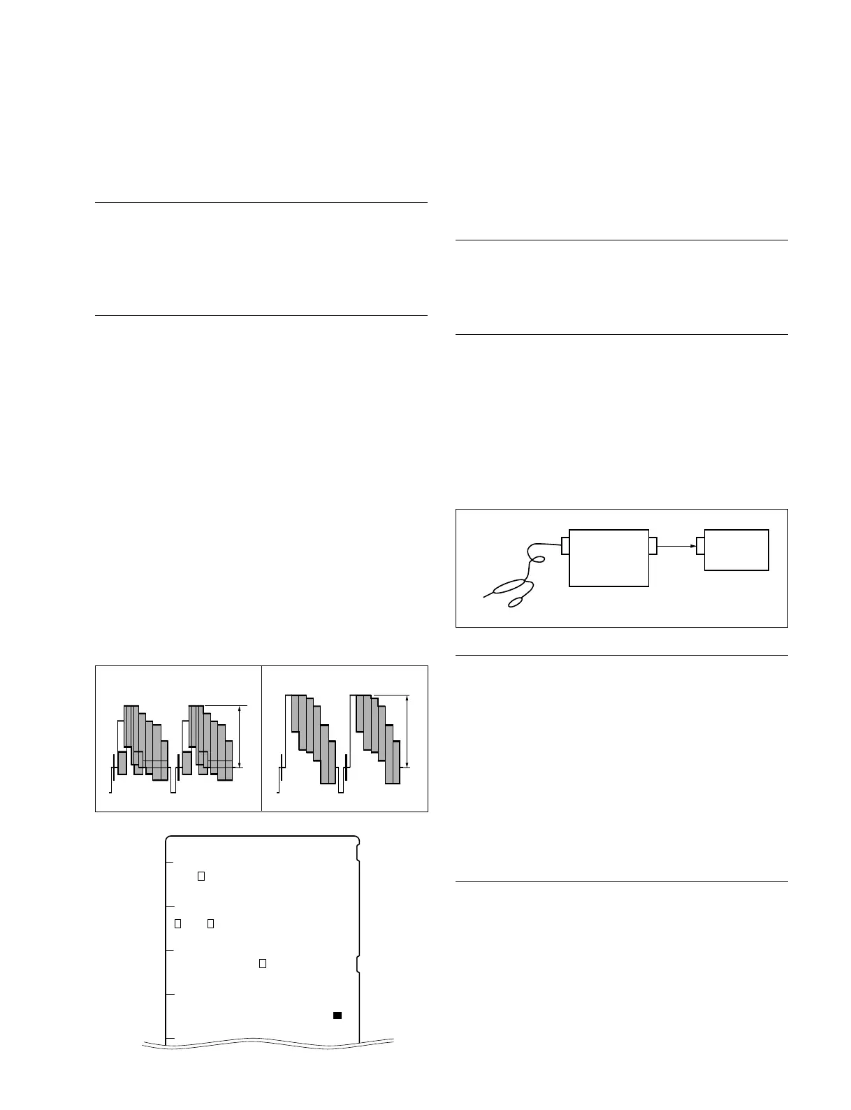
3-3-3. Prompter 1/2 Level Adjustment
Measures : SD waveform monitor (NTSC or PAL)
SD signal generator (NTSC or PAL)
Preparation
Connect the SD signal generator (for NTSC : SMPTE
color bar/for PAL : EBU color bar) to the PROMPTER IN
connector on the HDCU rear panel.
Adjustment Procedure
1. PROMPTER 1 level adjustment
Measuring point : PROMPTER 1 connector/CAMERA
side
Adjusting point : 1RV301 (G-1)/DTX-5 board
Specifications : A = 140 ± 1 IRE
(terminated at 75 Z) (for NTSC)
A = 1000 ± 7 mV p-p
(terminated at 75 Z) (for PAL)
2. PROMPTER 2 level adjustment
Measuring point : PROMPTER 2 connector/CAMERA
side
Adjusting point : 1RV701 (G-2)/DTX-5 board
Specifications : A = 140 ± 1 IRE
(terminated at 75 Z) (for NTSC)
A = 1000 ± 7 mV p-p
(terminated at 75 Z) (for PAL)
DTX-5 board (A side)
[for PAL]
[for NTSC]
A A
EFG HJ
1
1
1
RV251
RV701
RV301
TP301
TP351
TP501
TP701
TP251
3-4. Video Signal System Adjustment
(Front board)
3-4-1.
SD-SDI Input VCO Free-run Adjustment
Measure : Frequency counter, Oscilloscope
Note
After replacing IC251 on the DTX-5 board only, perform
this adjustment.
Preparation
. To be extended : DTX-5 board (front side)
. Disconnect the cables connected to the HD SDI1
connector on the HDCU rear panel, and the SD SDI1
connector on the HDCU rear panel.
. Connect the measure as shown in the following figure.
. After turning on the power, wait for 10 minutes at least
and start adjustment.
Adjustment Procedure
1. Measuring point : TP251 (E-4)/DTX-5 board
Adjusting point : 1RV251 (F-4)/DTX-5 board
Specifications : 27.0 ± 0.2 MHz
n
After finishing the adjustment and waiting for 10 minutes
at least, confirm that each specification is met.
If the specifications are not met, perform the adjustment
again.
Setting after Adjustment
After finishing the adjustment, reconnect the disconnected
cables.
Probe
Oscilloscope
Frequency
counter
CH2
IN
CH2
OUT
IN
 Loading...


