2-4 (E)
HDCU3300/MM (J, E)
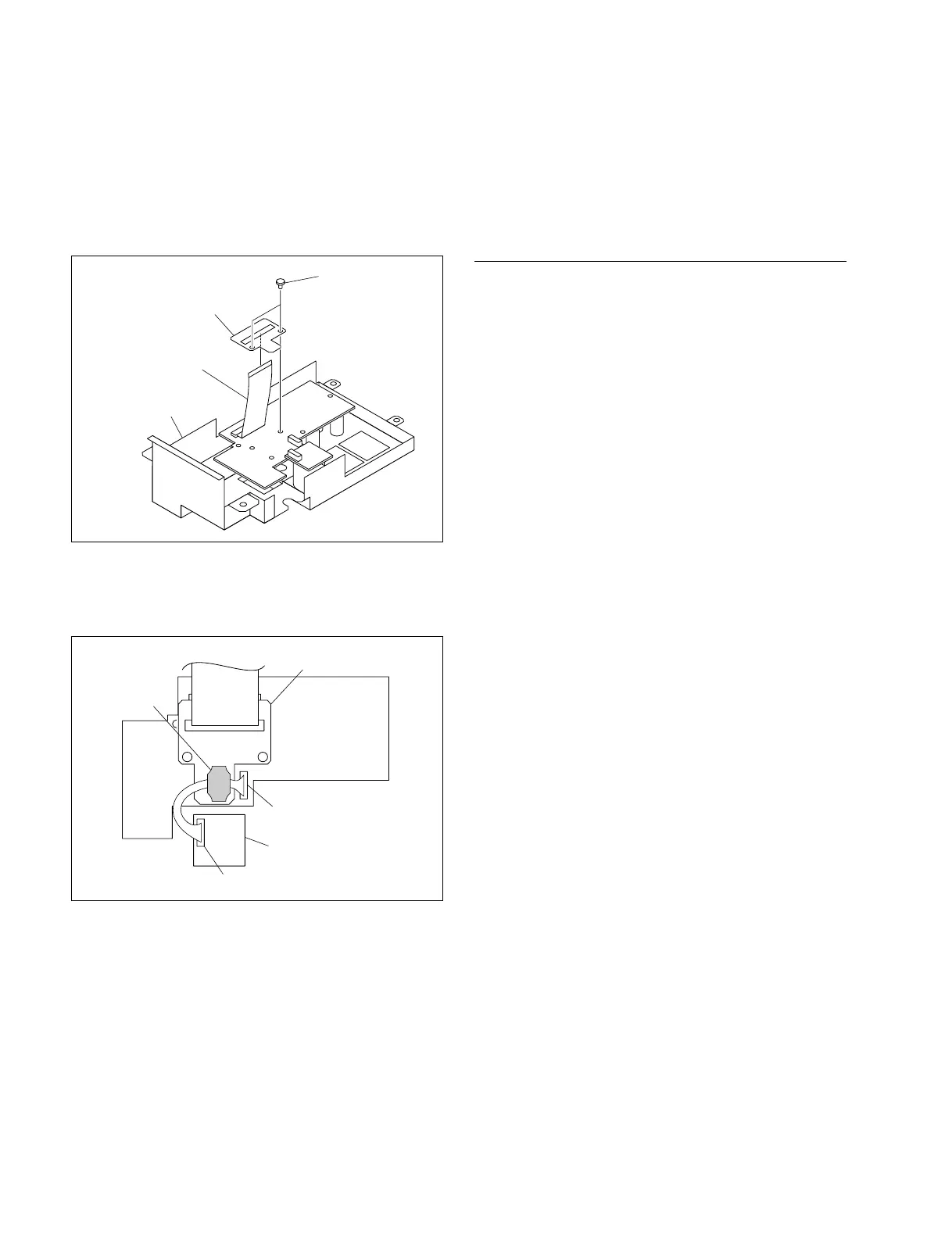
5. Install the CN-2700 board and the AU-302 board to
the PS panel assembly (X-2549-575-1) by reversing
steps 1 to 3.
6. Pass the protection sheet (AU-302) (3-986-514-02)
through the flexible card wire as shown in the figure
and secure it with the two rivets removed in step 4.
7. Push the ferrite core of the harness against the protec-
tion sheet (AU-302) (3-986-514-02) as shown in the
figure.
8. Install the PS panel assembly to the unit.
Rivets
PS panel assembly
Flexible card wire
Protection sheet (AU-302)
CN2
CN2
Ferrite core
Protection sheet (AU-302)
AU-302 board
CN-2700 board
2-1-2. Replacing the Fuse
w
The components marked ! are critical to safe operation. If
you replace with parts other than the specified ones, a fire
or electric shock may result from that.
Replacement Part
MAIN fuse
Part : Fuse (3.15 A, 250 V)
Part No. : ! 1-576-230-51
CAMERA fuse
n
Different types of camera fuses are used in the switching
regulator and the power block assembly (A10) as a power
supply unit.
Use the following specified fuses.
. Switching regulator (1-468-945-21)
For 100 to 120 V setting
Part: Fuse (6.3 A, 250 V)
Part No: ! 1-576-233-51
For 220 to 240 V setting
Part: Fuse (4 A, 250 V)
Part No: ! 1-576-231-51
. Power block assembly (A-1768-444-A)
For 100 to 120 V setting
Part: Fuse (8 A, 250 V)
Part No: ! 1-576-300-51
For 220 to 240 V setting
Part: Fuse (6.3 A, 250 V)
Part No: ! 1-576-233-51