— 11 —
KV-13FM13 / 13FM14
The following adjustments should be made when a complete
realignment is required or a new picture tube is installed.
These adjustments should be performed with rated power supply
voltage unless otherwise noted.
The controls and switch should be set as follows unless otherwise
noted:
PICTURE CONTROL: normal
BRIGHTNESS CONTROL: normal
SECTION 2: SET-UP ADJUSTMENTS
Perform the adjustments in order as follows:
1. Beam Landing
2. Convergence
3. Focus
4. Screen (G2)/White Balance
Test Equipment Required:
1. Color Bar Pattern Generator
2. Degausser
3. DC Power Supply
4. Digital Multimeter
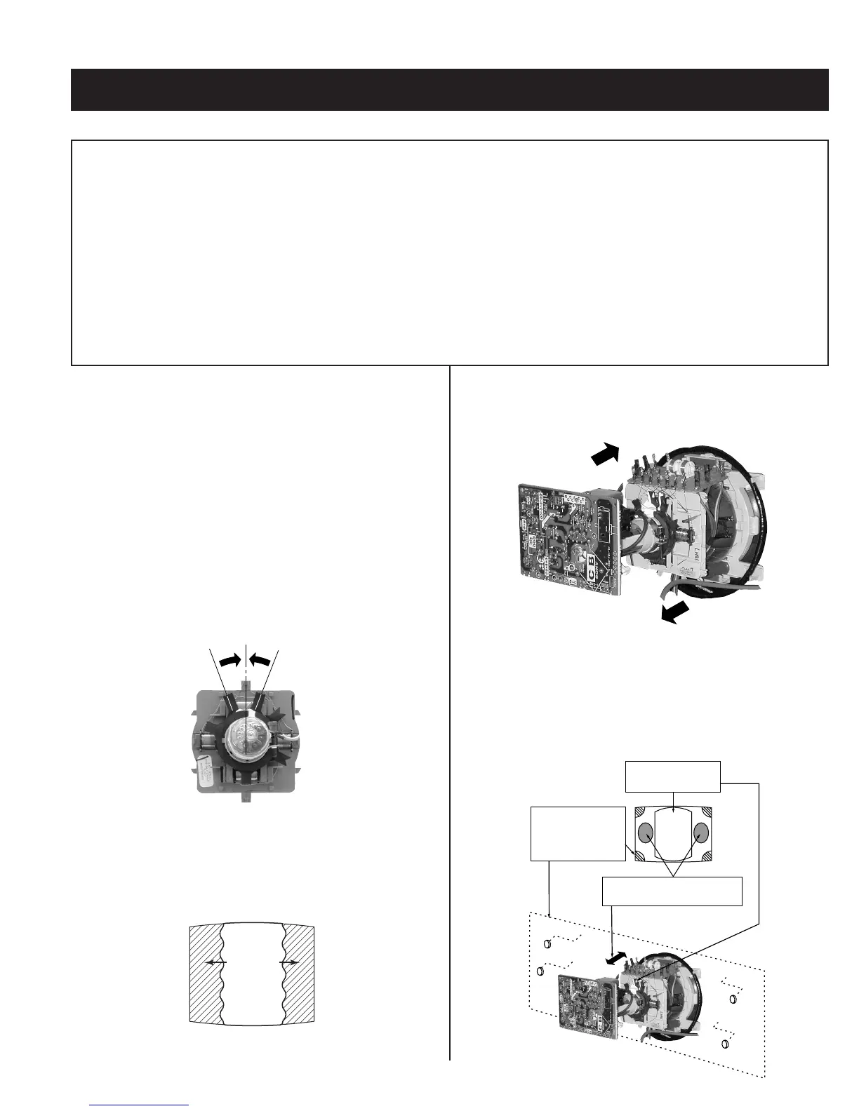
2-1. BEAM LANDING
Preparation:
• Degauss the entire screen.
• Feed in the white pattern signal.
Adjustment Procedure
1. Input a raster signal with the pattern generator.
2. Loosen the deß ection yoke mounting screw, and set the purity control
to the center as shown below:
Purity Control
3. Turn the raster signal of the pattern generator to green.
4. Move the deß ection yoke backward, and adjust with the purity control
so that green is in the center and red and blue are even on both
sides.
Blue Red
Green
5. Move the deß ection yoke forward, and adjust so that the entire screen
becomes green.
6. Switch over the raster signal to red and blue and conÞ rm the
condition.
7. When the position of the deß ection yoke is determined, tighten it with
the deß ection yoke mounting screw.
8. When landing at the corner is not right, adjust by using the disk
magnets.
a
c
b
d
ba
cd
Purity control
corrects this area
Disk magnets
or rotatable disk
magnets correct
these areas (a-d)
Deflection yoke positioning
corrects these areas