— 17 —
KV-13FM13 / 13FM14
SECTION 4: CIRCUIT ADJUSTMENTS
ELECTRICAL ADJUSTMENTS BY REMOTE COMMANDER
Use the Remote Commander (RM-Y172) to perform the circuit adjustments in this section.
Test Equipment Required: 1. Pattern generator 2. Frequency counter 3. Digital multimeter 4. Audio oscillator
4-1. SETTING THE SERVICE ADJUSTMENT MODE
1. Standby mode (power off).
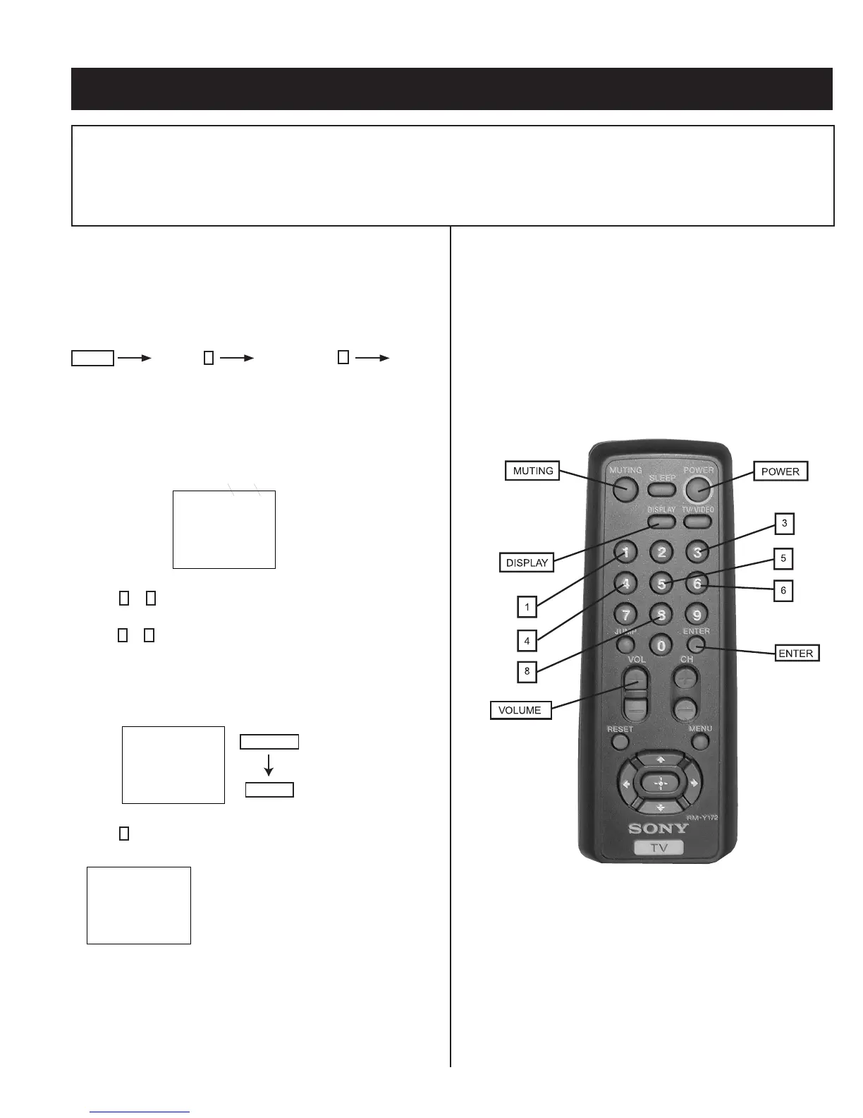
2. On the remote commander, press the following within one second
of each other:
Display
Channel
5
Sound Volume
+
Power
Service Adjustment Mode On
1. The CRT displays the item being adjusted.
SERVICE HSIZ 0
Disp.
(Item)
Item
Data
2. Press
1
or
4
on the Remote Commander to select an item.
3. Press
3
or
6
on the Remote Commander to change the data.
4. Press MUTING then ENTER to save into the memory.
Service Adjustment Mode Memory
SERVICE WRITE
Green
Red
MUTING
ENTER
1. Press
8
then ENTER on the Remote Commander to initialize.
SERVICE RESET
2. Turn set off then on to exit service adjustment mode.
Carry out step 1 when adjusting
IDs 0–4 and when replacing
and adjusting IC1003.
4-2. MEMORY WRITE CONFIRMATION METHOD
1. After adjustment, remove the power plug from the AC outlet, then
plug it in again.
2. Turn the power switch ON and set to service mode.
3. Call the adjusted items again to conÞ rm they were adjusted.
4-3. ADJUSTMENT BUTTONS AND INDICATORS
RM-Y172