– 19 –
FM FREQUENCY COVERAGE
CHECK
Frequency Display 87.5 MHz 108 MHz
Reading on Digital voltmeter 1.4 ± 0.2 V 6.9 ± 0.2 V
Adjustment Part <confirmation> <confirmation>
FM TRACKING CHECK
Adjust for a maximum reading on level meter.
<confirmation> <confirmation>
87.5 MHz 108 MHz
MW FREQUENCY COVERAGE
ADJUSTMENT
Frequency Display 531 kHz 1,611 kHz
Reading on Digital voltmeter 0.9 ± 0.1 V 4.9 ± 0.5 V
Adjustment Part L5 <confirmation>
AM IF ADJUSTMENT
Adjust for a maximum reading on level meter.
T1
450 kHz
MW TRACKING ADJUSTMENT
Adjust for a maximum reading on level meter.
L3 CT1
621 kHz 1,404 kHz
LW FREQUENCY COVERAGE
ADJUSTMENT
Frequency Display 153 kHz 279 kHz
Reading on Digital voltmeter 0.7 ± 0.2 V 5.2 ± 0.1 V
Adjustment Part <confirmation> CT3
LW TRACKING ADJUSTMENT
Adjust for a maximum reading on level meter.
L4 CT2
162 kHz 261 kHz
Adjustment Location: TUNER board (See page 20.)
5-2. TUNER SECTION 0 dB = 1 µV
Precautions in Repairing
Note : As a tuner unit (TU1) is difficult to repair if faulty,
replace it with new one.
• FM Section
Setting:
BAND button: FM
22.5 kHz frequency
deviation by 400 Hz signal
output level : as low as possible
• MW/LW Section
Setting:
BAND button: MW or LW
30% amplitude
modulation by 400 Hz signal
output level : as low as possible
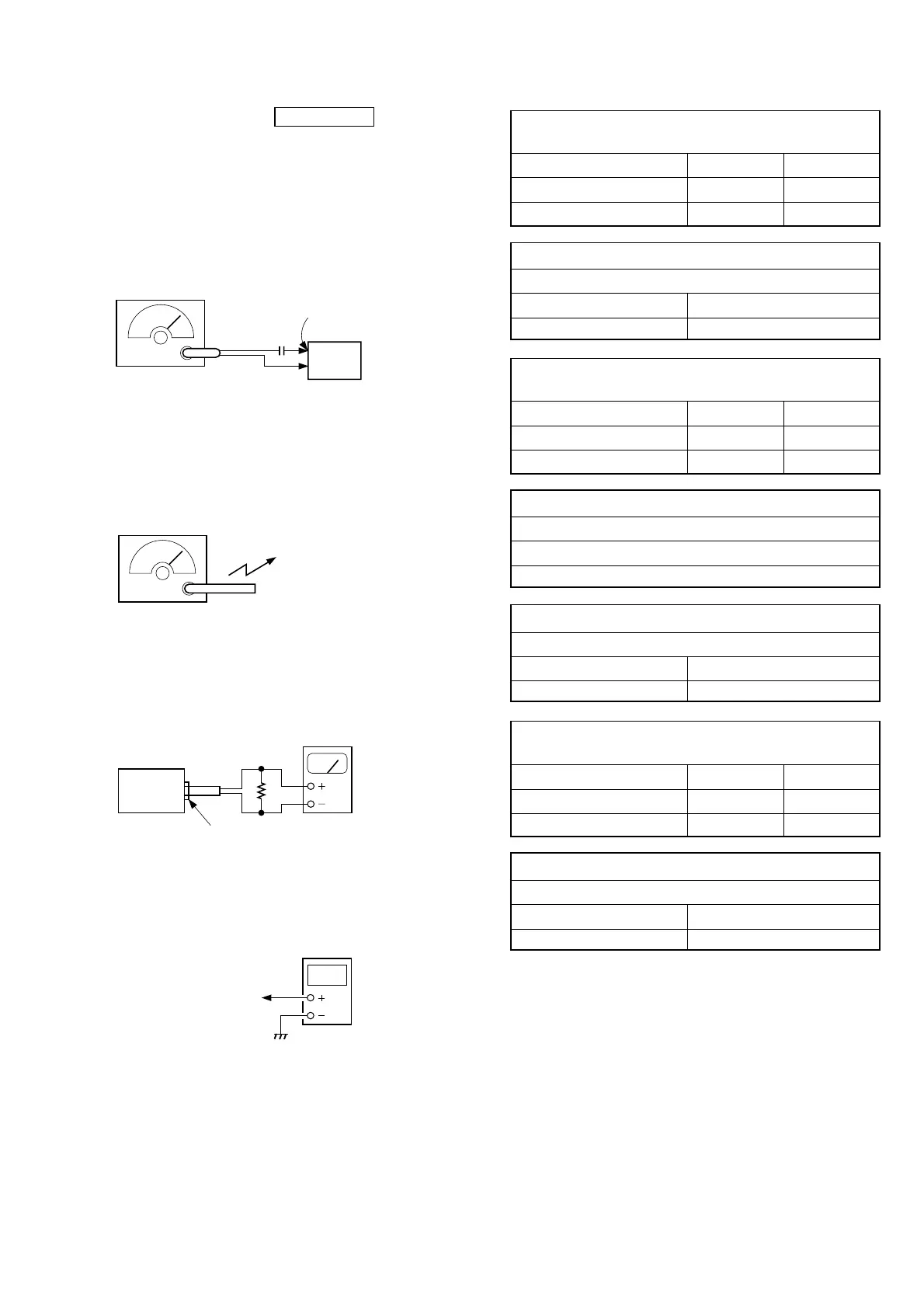
• Connecting Level Meter (FM, MW and LW)
• Connecting Digital Voltmeter (FM, MW and LW)
• Repeat the procedures in each adjustment several times, and the
frequency coverage and tracking adjustments should be finally
done by the trimmer capacitors.
FM termina
(J1)
FM RF signal
generator
0.01 µF
set
Put the lead-wire
antenna close to
the MW/LW loop
antenna.
AM RF signal
generator
i (headphones) jack (J301)
set
32 Ω
level meter
(range: 0.5-5 V ac
digital
voltmeter
tuner board
TP (VT)


 To Next Page