– 2 –
Dimensions (incl. projecting parts)
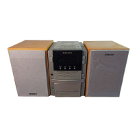
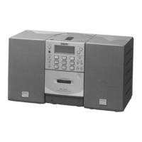
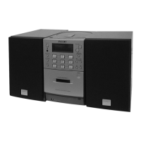
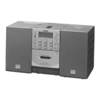
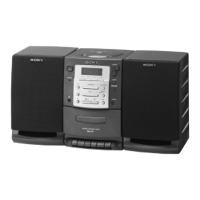
Player: approx. 137 × 212 × 202 mm (w/h/d)
(5 1/2 × 8 3/8 × 8 inches)
Left speaker: approx. 137 × 212 × 202 mm
(w/h/d) (5 1/2 × 8 3/8 × 8 inches)
Right speaker: approx. 137 × 180 × 202 mm
(w/h/d) (5 1/2 × 7 1/8 × 8 inches)
Mass
Player: approx. 1.8 kg (3 lb. 15 oz.)
Left speaker: approx. 3 kg (6 lb. 10 oz.)
Right speaker: approx. 1.5 kg (3 lb. 5 oz.)
Supplied accessories
Remote control (1)
FM lead aerial (1)
MW/LW loop aerial (1)
Audio connecting cord (1)
Design and specifications are subject to change without
notice.
TABLE OF CONTENTS
1. SERVICING NOTES......................................................... 3
2. GENERAL
Playing a CD ........................................................................... 4
Listening to the radio............................................................... 4
Playing a tape .......................................................................... 5
Recording on a tape ................................................................. 5
3. DISASSEMBLY
3-1. Cabinet (Front) Assy ........................................................... 7
3-2. Cabinet (Rear) ..................................................................... 8
3-3. Front Board ......................................................................... 8
3-4. Control Board...................................................................... 9
3-5. Line Board........................................................................... 9
3-6. Tuner Board ....................................................................... 10
3-7. Holder, Cassette ................................................................ 10
3-8. Top Block Assy ................................................................. 11
3-9. CD Mechanism Block ....................................................... 11
3-10. H/P Board.......................................................................... 12
3-11. Main Board ....................................................................... 12
3-12. Tape Mechanism Block ..................................................... 13
3-13. Top Board .......................................................................... 13
3-14. Plate Assy, Chuck .............................................................. 14
3-15. Tray ................................................................................... 14
3-16. Loading Board................................................................... 15
3-17. CD Board .......................................................................... 15
3-18. CD Mechanism Block ....................................................... 16
3-19. Power Board ...................................................................... 16
4. MECHANICAL ADJUSTMENTS............................... 17
5. ELECTRICAL ADJUSTMENTS
5-1. Tape Section ...................................................................... 17
5-2. Tuner Section .................................................................... 19
5-3. CD Section ........................................................................ 21
6. DIAGRAMS
6-1. IC Pin Descriptions ........................................................... 24
6-2. Circuit Boards Location .................................................... 26
6-3. Block Diagram –Tuner Section– ....................................... 27
6-4. Block Diagram –CD Section–........................................... 29
6-5. Block Diagram –Tape Section– ........................................ 31
6-6. Block Diagram –System Control, Power Section– ........... 33
6-7. Printed Wiring Board –Tuner Section– ............................. 35
6-8. Schematic Diagram –Tuner Section– ................................ 37
6-9. Printed Wiring Boards –CD Section– ............................... 39
6-10. Schematic Diagram –CD Section–.................................... 41
6-11. Printed Wiring Board –TC Section– ................................. 43
6-12. Schematic Diagram –TC Section– .................................... 45
6-13. Printed Wiring Board –Main Section– .............................. 47
6-14. Schematic Diagram –Main Section–................................. 49
6-15. Printed Wiring Board –Control Section– .......................... 51
6-16. Schematic Diagram –Control Section– ............................. 55
6-17. Printed Wiring Board –Front Section–.............................. 57
6-18. Schematic Diagram –Front Section– ................................ 58
6-19. Printed Wiring Board –Top Section– ................................ 59
6-20. Schematic Diagram –Top Section– ................................... 60
6-21. Printed Wiring Board –Line Section– ............................... 61
6-22. Schematic Diagram –Line Section–.................................. 61
6-23. Printed Wiring Boards –Power Section–........................... 63
6-24. Schematic Diagram –Power Section– ............................... 65
6-25. IC Block Diagrams............................................................ 67
7. EXPLODED VIEWS
7-1. Cabinet Section ................................................................. 72
7-2. Cabinet (Top) Section ....................................................... 73
7-3. CD Chassis Section ........................................................... 74
7-4. Mechanism Deck Section (1) ............................................ 75
7-5. Mechanism Deck Section (2) ............................................ 76
7-6. Optical Pick-up Section .................................................... 77
7-7. Speaker (L) Section........................................................... 78
7-8. Speaker (R) Section........................................................... 79
8. ELECTRICAL PARTS LIST......................................... 80