2
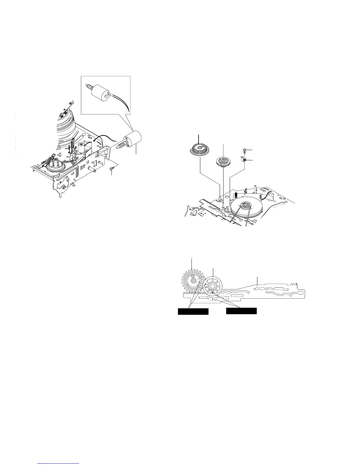
MOTOR LOADING ASS`Y
1
SCREW
2-4-7 Motor Loading Ass’y Removal
1) Remove the screw 1.
2) Remove the Motor Loading Ass’y 2.
Fig.2-18 Motor Loading Ass’y Removal
2-4-8 Bracket Gear, Gear Joint 2, 1 Removal
1) Remove the SCREW 1.
2) Remove the Bracket Gear 2.
3) Remove the Gear Joint 2 3.
4) Remove the Gear Joint 1 4.
Assembly:
1) Be sure to align dot mark of Gear Joint 1 1 with dot mark of
Gear Joint 2 2 as shown Fig 2-20.
(Refer to Timing point1)
2) Confirm the Timing Point 2 of the Gear Joint 2 2 and Slider
Cam 3.
Fig. 2-19 Bracket Gear, Gear Joint 1,2 Removal
Fig. 2-20 Gear Joint 1,2 Assembly
1
GEAR JOINT1
2
GEAR JOINT2
3
SLIDER CAM
TIMING POINT 1
TIMING POINT 2