2-11
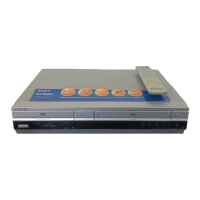
2-4-9 Gear Loading Drive, Slider Cam,
Lever Load S, T Ass’y Removal
1) Remove the Belt Pulley. (Refer to Fig. 2-38)
2) Remove the Gear Loading Drive 1 after releasing Hook [A] in
the direction arrow as shown in detail drawing.
3) Remove the Slider Cam 2.
4) Remove the Lever Load S Ass’y 3 & Lever Load T Ass’y 4.
Fig. 2-21 Gear Loading Drive, Slider Cam,
Lever T, S Load Ass’y Removal
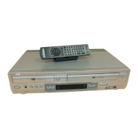
2-4-10 Gear Loading Drive, Slider Cam,
Lever Load S, T Ass’y Assembly
1) When reinstalling, be sure to align dot of Lever Load T Ass’y
1 with dot of Lever Load S Ass’y 2 as shown in drawing,
(Refer to Timing Point 1).
2) Insert the Pin A,B,C,D into the Slider Cam 3 hole,
3) Be sure to align dot of Lever Load T 1 and dot of Gear Loading
Drive 4, (Refer to Timing Point 2).
4) Aline dot of Gear Loading drive 4 with mark of Slider Cam 3
as shown in drawing (Refer to Timing Point 3).
Fig. 2-22 Gear Loading Drive, Slider Cam,
Lever Load S, T Ass’y Assembly
1
GEAR LOADING DRIVE
3
LEVER LOAD S ASS'Y
4
LEVER LOAD T ASS'Y
2
SLIDE CAM
HOOK(A)